What is Design Intent?
Design Intent!
A review of the design criteria to establish how to model the part to allow as much design flexibility as the design develops.
Why do we need Design Intent?
The Pro/e paradigm of history only design based on constrained sketching is very unforgiving when making changes.
What are the considerations? Only Simplicity! We know that this can completely disappear as the modeling proceeds. The creation of a functional model comes with knowledge and experience. That is what makes the “Pro/e paradigm” so experience and intelligence sensitive.
Is 3D CAD Productivity an Oxymoron?
My Introduction to Design Intent
In 2001 I decided to sell Pro/e when it moved to the PC. I took my first class and was informed that you need look at the scope of the part before starting the model. I was told this was called “Design Intent”.
I scratched my head! I had been selling CADKEY and IronCAD. CADKEY was a Boolean direct edit modeler and IronCAD was the only true integrated History/Direct edit modeler using a unique drag and drop of shapes from a catalog with integrated direct edit as part of the design process. I never concerned myself with a design process it was always very flexible.
So, all of this was very new and strange to me.
As I got introduced to Pro/e, I quickly found it was far too complex to sell for a small CAD dealer. I did a bit of work with Pro/e and it just took too much time for the simplest of designs.
Actually I was introduced to Solidworks in 1998 and was offered a dealership. Many CADKEY dealers were moving to SW. I played with it a bit and found the same limitations of Pro/e, but I was already using IronCAD that was history-based system that used drag and drop, sketching, integrated direct edit and face modification. This was a much more advanced flexible design system.
Design Intent Revisited
Craig, a good friend and associate decided to try ZW3D, one of TECH-NET, Inc’s products. He is a professional highly skilled CNC programmer and manufacturing expert. He was interested in ZW3D’s integrated CNC.
ZW3D is a history sketch-based system, much like Pro/e and all the other popular programs. The difference that makes ZW3D worth selling it that it has a multi-object environment, integrated professional surfacing and integrated drawings so you can have small projects including subassemblies in a single file.
Craig has been a CADKEY and IronCAD user for decades, so like me, modeling in a Pro/e sketch based design system was a bit confusing and required a bit of a paradigm shift.
As he trained he would send me simple models. But as he advanced so did his models. That last one was fairly complicated, and he was stuck.
Here is the email Craig sent!
Hi Joe,
Attached is a file where I’d like to use a Boolean operation to create all the faces and shapes into one model — like we do in IronCAD. How is this done in ZW? When I try to combine the faces and shapes. I get a mess where some of the faces/shapes are trimmed weird or just dropped altogether.
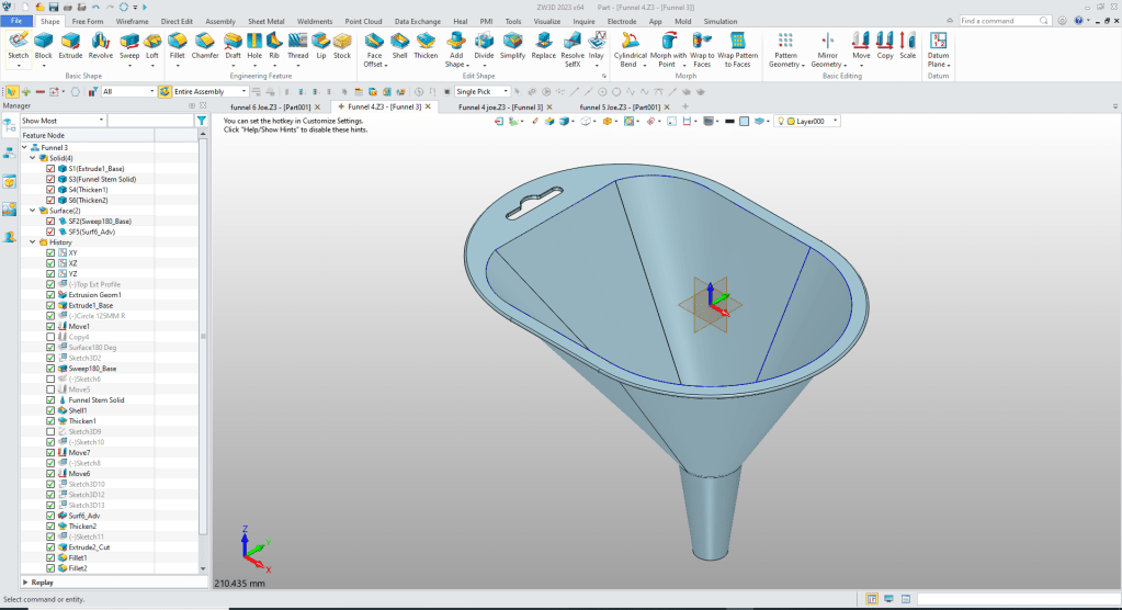
I decided to see how to fix Craig’s problem.
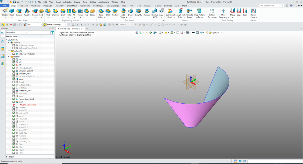
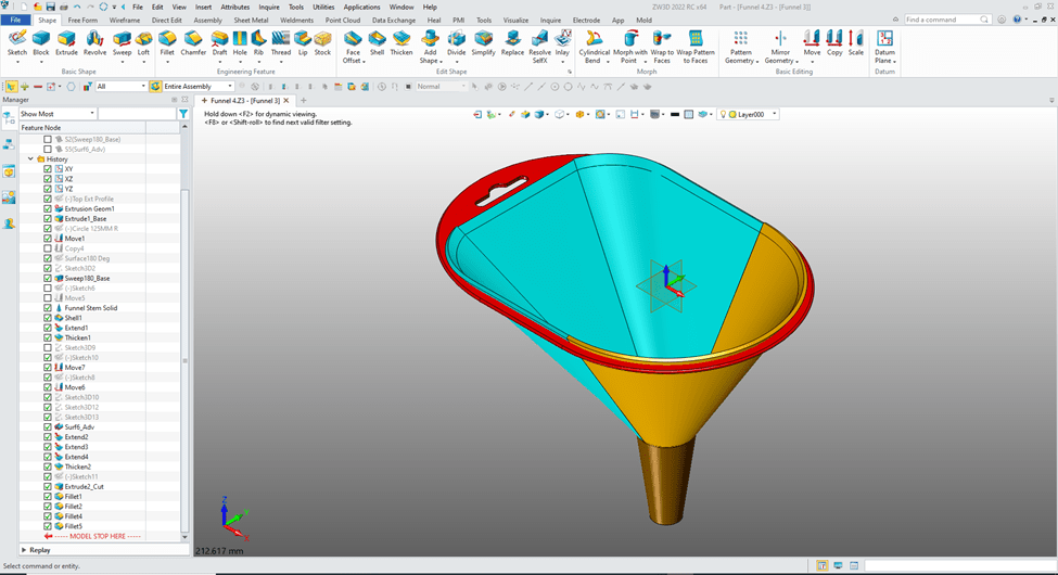
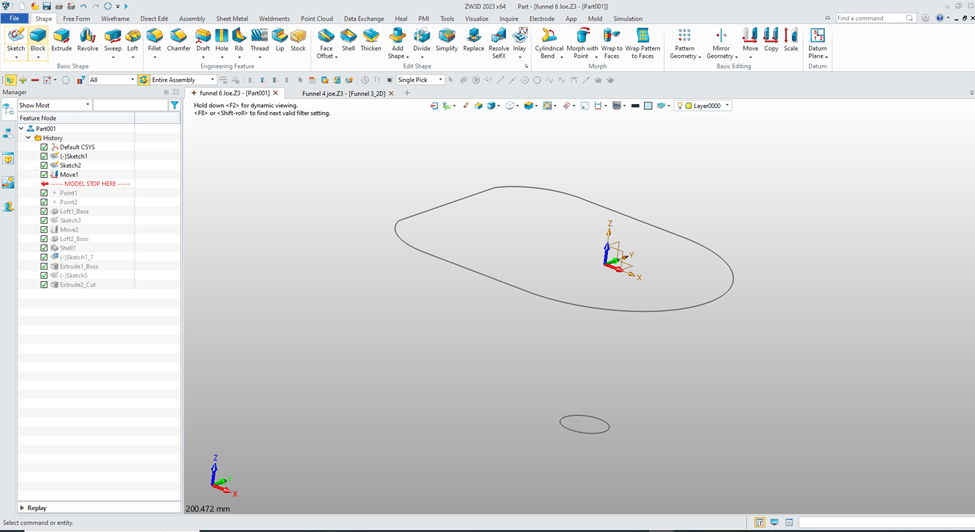
I started to scrutinize the part and found 4 separate solids.
You can see them here.
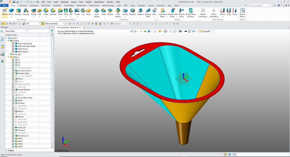
I found the red part was an imported part. And the blue and yellow were based on these surfaces.
Now this is where the lack of “Design Intent” shows its ugly face. Would I have designed with surfaces? No. But Craig wants to learn the advanced surfacing functionality of ZW3D because he is in the business that designs Kayaks. So he probably wasn’t thinking in solids only. ZW3D has integrated solid/surfacing using many of the same commands with just an option if it to be a solid or surface.
I realized there were coincidental edges on the top solid that were stopping the successful combining of the shape.
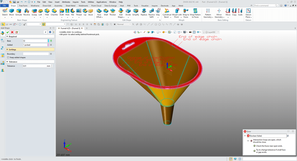
Now, If I extend the inside surface that would give the results I want. Now, we are just are attempting to get the model to be complete. I realized this model would have future problems and should be remodeled with a bit more “Design Intent”.
Let’s fix it a very easy way.
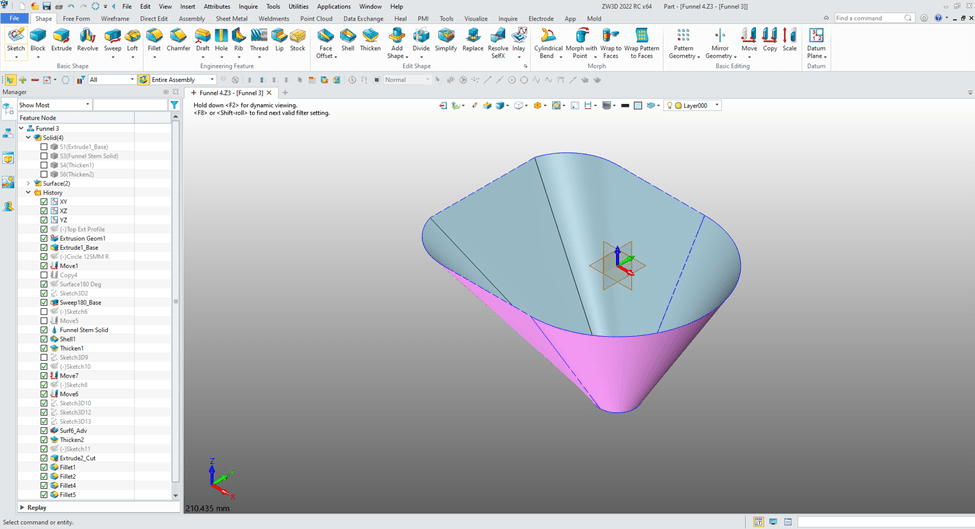
We back out of this command and only work with the surfaces. We blank all solids.
We will extend the surfaces 5mm.
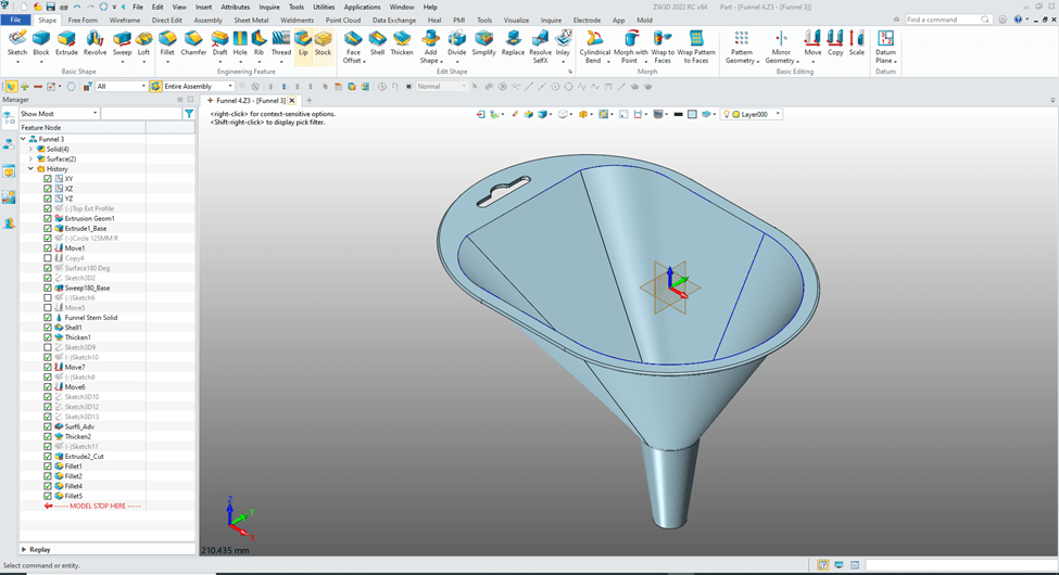
We move the “Model Stop Here” up before the first thicken command.
We go to the free form tab and select “Extend Faces”.
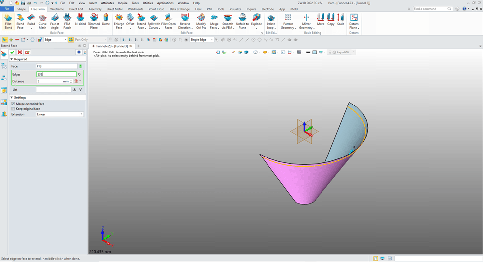
We need to extend the other surfaces.
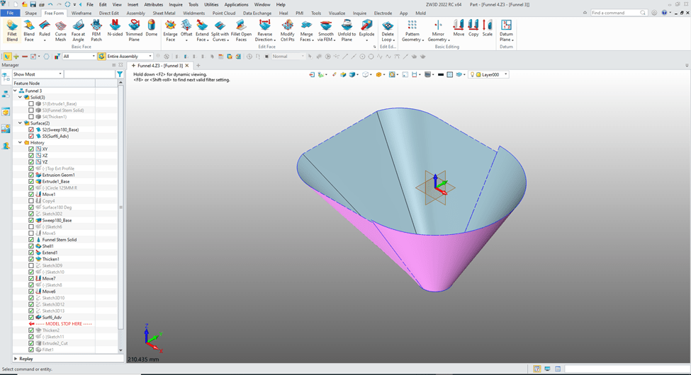
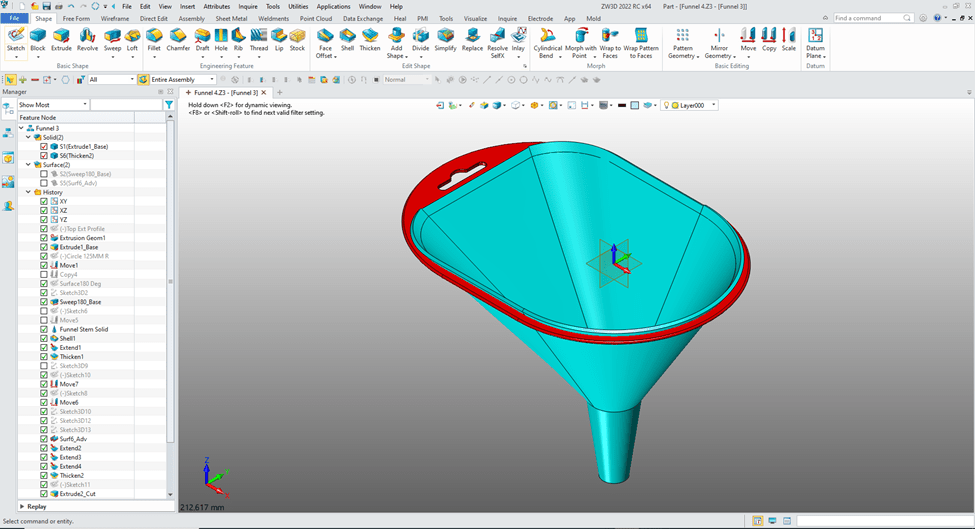
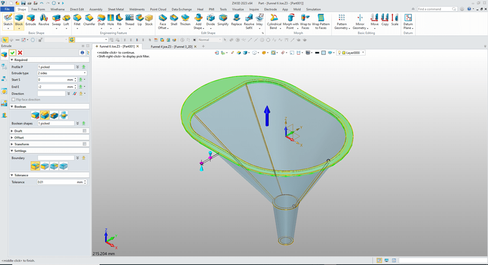
We extend the other 3 faces and move the “Model Stop Here” to the end of the history and turn on the solids and blank the surfaces.
You can see our surfaces have been thickened. Now I have played with the combine and found that combining the bottom three solids gives me the place where I can trim the resulting extended solids.
So let’s combine the solids.
We create a sketch on the X0Y0 plane can just sketch a rectangle large enough to include the affected edges.

We exit the sketch and extrude the sketch enough to include the edges set to remove and trim the bottom solid.
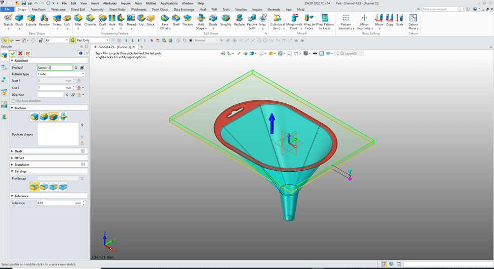
We combine the top to bottom and we now have a workable model, but not an optimum model.
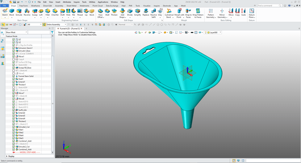
Now there may be many ways to fix this model. This was just one. But with a bit of “Design Intent” and a good working knowledge of the program we can avoid these problems.
Let’s create this model to assure we have a good part.
As we know this part can be modeled may different ways. We have to look at it and recognize the design intent so as to not be put in a corner and have to go back to modify or recreate. Now, creating a model from a drawing is much different than initial design. With initial design you have to have a good understand the form, fit and function of the part before starting.
Here is a drawing if you would like to model the part!
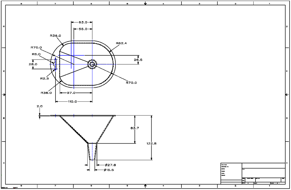
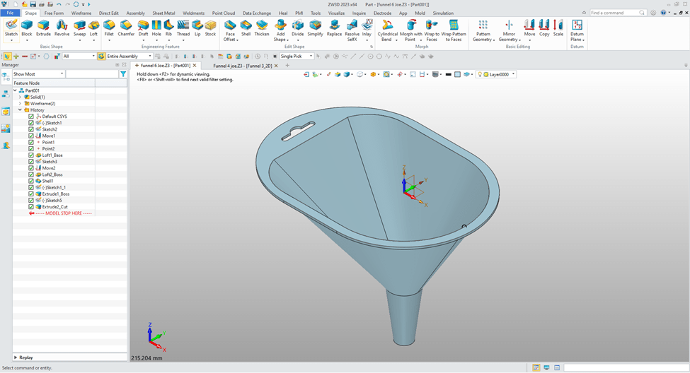
ZW3D as a unique very clear history format. I will go through each step.
I decided with my knowledge of ZW3D starting with the funnel shape would be the most optimum way of creating part.
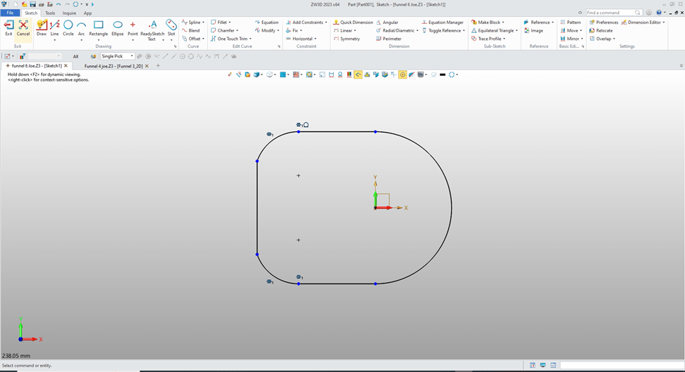
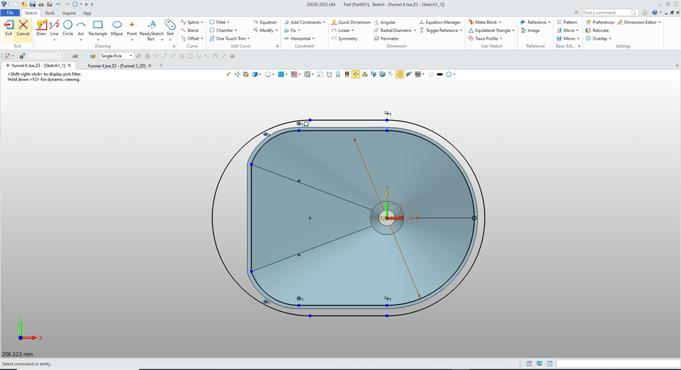
I create a sketch of the top of the funnel. As you can see I do not use constrained sketching. Most graphics are create with parallel lines and using the entities for reference locations. I call this “StreamLined Sketching”.
StreamLined Sketching is like you would draw it on a drafting board or in 2D. I am sure many have not even made a manual drawing. But manually you create parallel and angled lines using a straight edge, drafting machine, triangles, compasses and circle templates. Yes, you used an eraser for trim.
I will then create a new sketch at X0Y0 plane and create the bottom circle of the base funnel.
Then move it to the correct location.
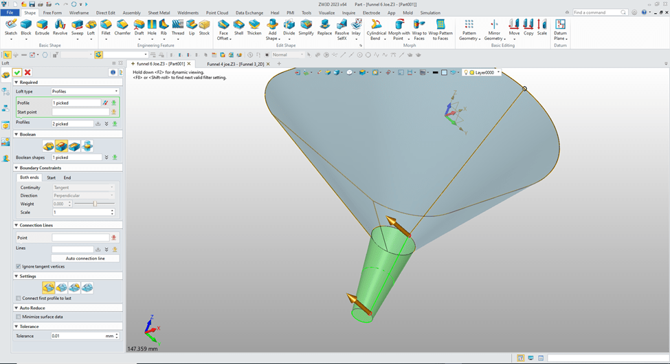
I now create the loft. I create two reference points to assure there are no twists in our loft.

I create the circle for the bottom feature at X0Y0 plane and move to it to the correct location.

Again we use the loft command and create the bottom feature selecting the add option.
We now are going to shell outward 2 mm.

We will copy and paste the first sketch and edit it for the top Feature. Again you see that I have not used any constraints.
Now we just extrude the sketch the 2mm and set the option to add.
We now create a sketch at X0Y0 plane, sketch the hole in the top piece using ‘StreamLined Sketch” no constraints.

We extrude the hole.

No problems with this model. “Design Intent” was effectively used!
We have some great lessons comparing IronCAD and ZW3D to other popular modeling systems using Feature Based Modeling and StreamLined Sketching.
3D Modeling Techniques Defined
Please feel free to stop by our website below for a variety of articles on the State of our Industry, interesting articles on 3D CAD Productivity and a few of our projects!

Viewpoints on Today’s 3D CAD and Engineering Industry
TECH-NET Engineering Services!
We sell and support IronCAD and ZW3D Products and
provide engineering services throughout the USA and Canada!
Why TECH-NET Sells IronCAD and ZW3D
If you are interested in adding professional hybrid modeling capabilities or looking for a new solution to increase your productivity, take some time to download a fully functional 30 day evaluation and play with these packages. Feel free to give me a call if you have any questions or would like an on-line presentation.
For more information or to download IronCAD or ZW3D
Joe Brouwer
206-842-0360
