Please go to here to see the other lessons.
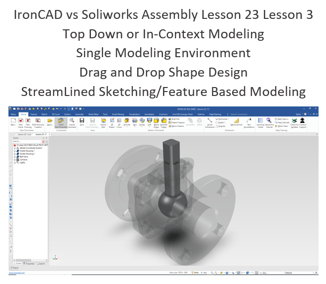
IronCAD vs Solidworks Assembly Lesson 23
What is the advantage designing with shapes?
Using shapes eliminates the need to create a sketch and extrude or revolve. If you created each feature individually it is easier to modify directly. Imagine a complex part. Give this concept a try today.
Design of Water Control Valve in Solidworks
IronCAD vs Solidworks
While creating 3D models from drawing is the very best way to learn 3D CAD and maybe some design techniques is does not expose the designer to the design flexibility necessary in product design. IronCAD is all top down due to the single model environment. Creating mating parts is a cruise. But modeling is just one aspect of this well designed productive 3D CAD system.
I like to show step by step lessons So you can see the commands being used.
I always create the part before I watch the Video, so as to not taint my process. Of course, there are a multitude of ways to create a model. There is no right way, just more productive ways. From what I have seen from these very complicated processes done by the Solidworks Presenters, it is not just limited by the 3D CAD system.
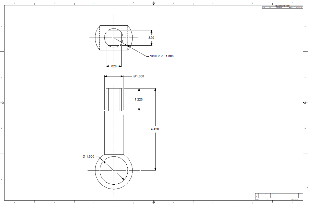
Here is the drawing if you would like to follow along.
For more information or to download IronCAD
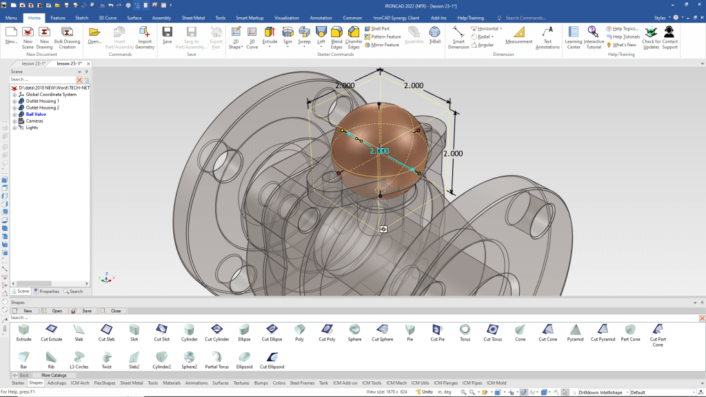
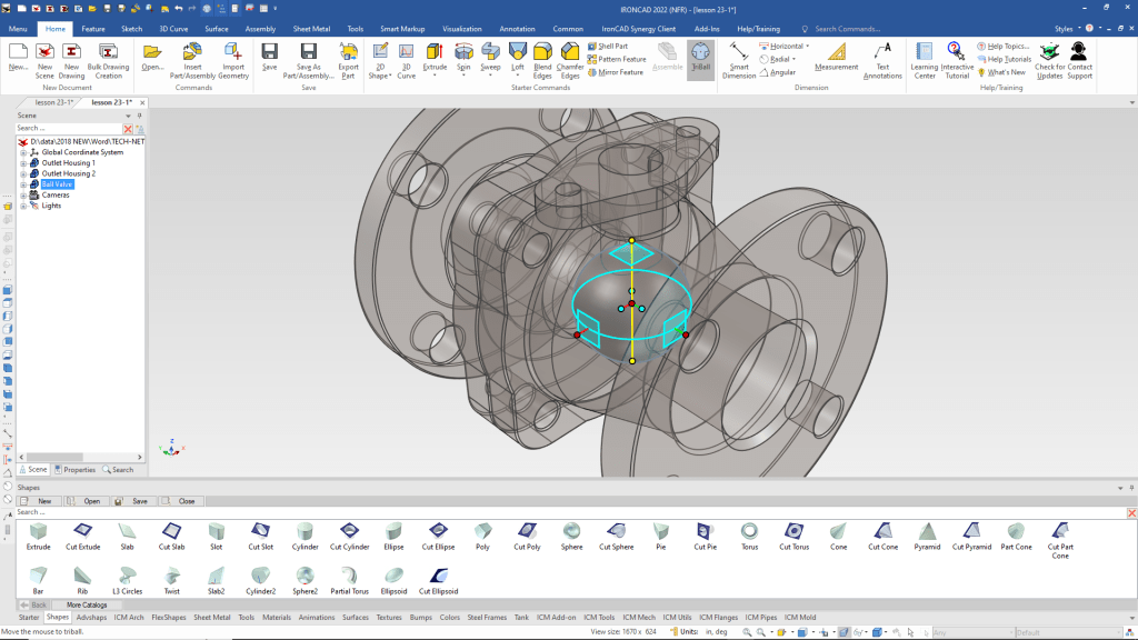
We we drag and drop a sphere on the center of the flange. When dragging and dropping a feature, part or an assembly out of the catalog IronCAD recognizes centers, mid-points and corners.
That will create a new part in the Scene Browser, we rename the part. We do not call it history since it has separate part, assemblies, sketches, surfaces, curves and more. We change the color and set it to active to for more clarity.
We select the part and using the Tribal we select the vertical axis, select the inside dot with the right mouse button and select “To Center Point” and select the center hole from the dialog box.
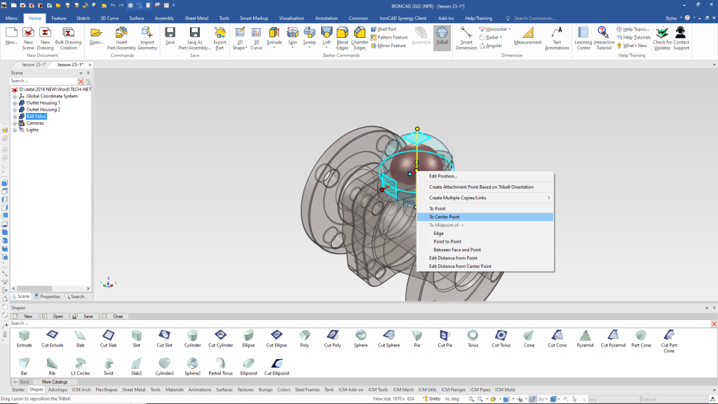
You can see the sphere has moved to the center of the hole.
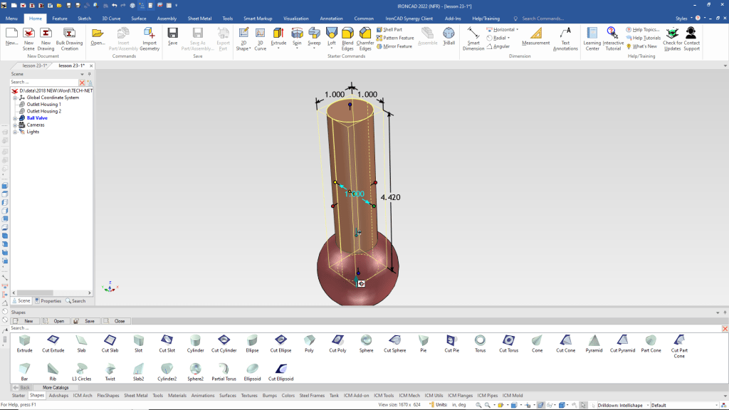
That was all we needed from the other parts for top down design so we hide the other parts. We drag and drop a cylinder to the top of the sphere.
We size the diameter of the cylinder and push/pull the handle to the center of the sphere and the set the height.
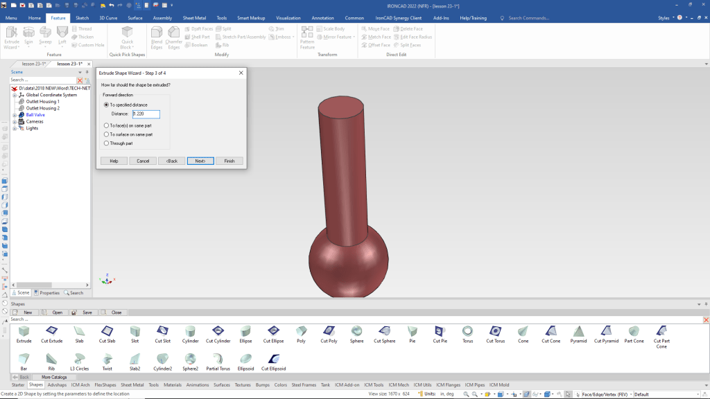
We use the “Extrude Wizard” to create a sketch plane on the top of of the cylinder and set the depth of the extrusion.
We use the “Center Rectangle” command using the right mouse button that brings up a dialog box for the dimensions. This is available for all entities.
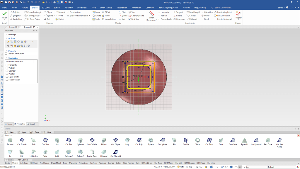
We select okay and our extrusion is done.
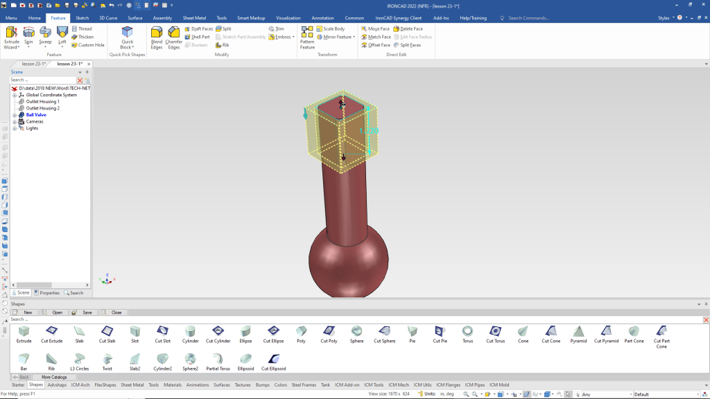
Now for the hole through the middle of the sphere. We drag and drop a cut cylinder on to the face of the previous cut to set the orientation. We size it and use the Triball to move to the center of the sphere.
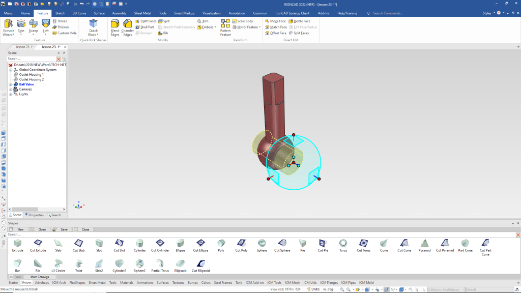
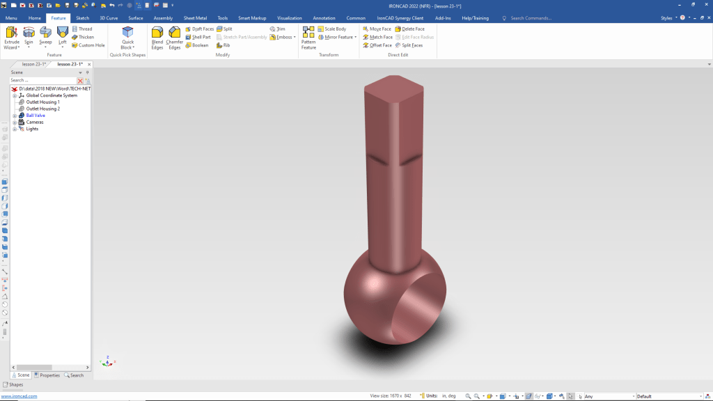
We are done with the part. We hid the catalog for a larger and better view of the part. I use the auto-hide catalog feature when design. I show it during the exercise to understand the we can have standard of custom catalogs.
Please go to here to see the other lessons.
IronCAD vs Solidworks Assembly Lesson 23
It is very important that you look into how you or your engineers are creating the parts. Streamline Sketching and Feature Based Modeling is easy to learn and implement. It, alone, will increase productivity 10X. Now, IronCAD with its unique integrated history/direct edit functionality can increase your productivity another 5X or more with changes! Again, time is money in engineering.
More on Streamline Sketching and Feature Based Modeling.
3D Modeling Techniques Defined
To experience this increased level of productivity, please download IronCAD for a 30 day evaluation. Legacy data is no problem, IronCAD can read the native files of all of the popular programs. IronCAD is a great replacement for the subscription only Autodesk and PTC products.
For more information or to download IronCAD
Give me a call if you have any questions. I can set up a skype or gotomeeting to show this part or answer any of your questions on the operation of IronCAD. It truly is the very best conceptual 3D CAD system.
TECH-NET Engineering Services!
We sell and support IronCAD and ZW3D Products and
provide engineering services throughout the USA and Canada!
Why TECH-NET Sells IronCAD and ZW3D
If you are interested in adding professional hybrid modeling capabilities or looking for a new solution to increase your productivity, take some time to download a fully functional 30 day evaluation and play with these packages. Feel free to give me a call if you have any questions or would like an on-line presentation.
For more information or to download IronCAD or ZW3D
Joe Brouwer
206-842-0360
