
Please go to here to see the other lessons.
IronCAD vs Solidworks Assembly Lesson 26
What is the advantage designing with shapes?
Using shapes eliminates the need to create a sketch and extrude or revolve. If you created each feature individually it is easier to modify directly. Imagine a complex part. Give this concept a try today.
Design of Feed check Valve in Solidworks | Solidworks Exploded View
IronCAD vs Solidworks
While creating 3D models from drawing is the very best way to learn 3D CAD and maybe some design techniques is does not expose the designer to the design flexibility necessary in product design. IronCAD is all top down due to the single model environment. Creating mating parts is a cruise. But modeling is just one aspect of this well designed productive 3D CAD system.
I like to show step by step lessons So you can see the commands being used.
I always create the part before I watch the Video, so as to not taint my process. Of course, there are a multitude of ways to create a model. There is no right way, just more productive ways. From what I have seen from these very complicated processes done by the Solidworks Presenters, it is not just limited by the 3D CAD system.
Here is the drawing if you would like to follow along.
For more information or to download IronCAD
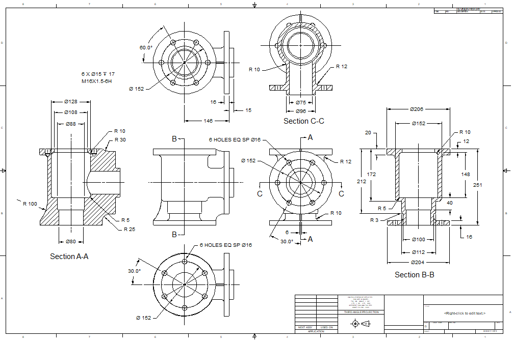
I call this type of design Feature Based Design. As we review this model we can see that we many cylindrical shapes. We see the main body is a cylinder.
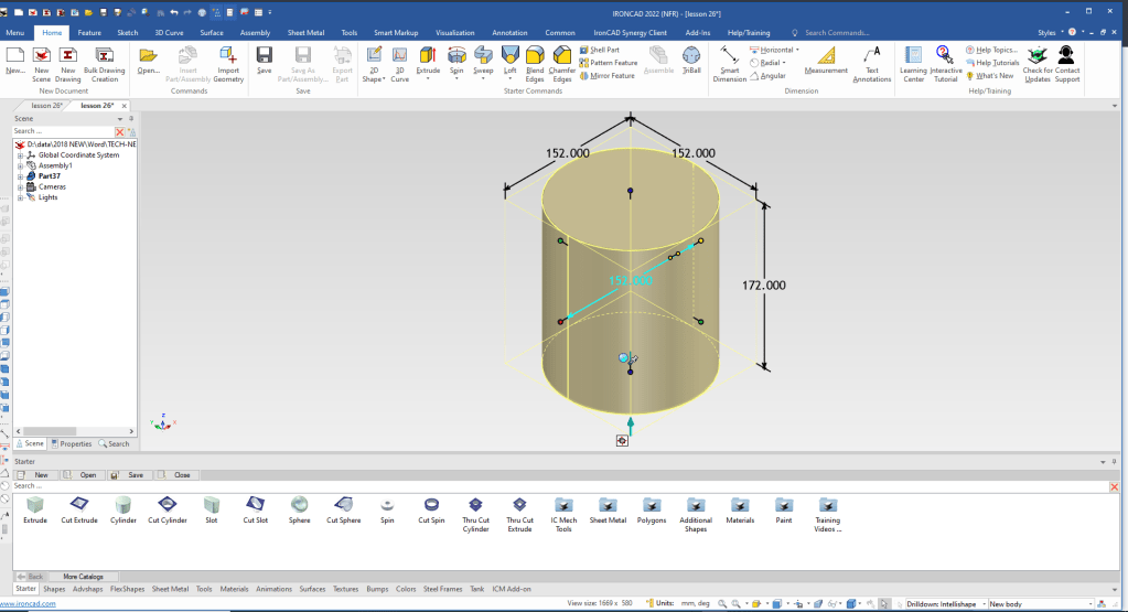
So we will drag and drop a cylinder into the scene, orientated it (with the Triball) and size it.
Note: Why does IronCAD call it a scene instead of a workspace? IronCAD was first released as a graphic design program called Trispectives. It still has much of the graphic design functionality. It truly is a wonderful mixture of professional 3D CAD and graphic design, which puts it in a much more flexible category as compared to the Pro/e (Creo) clones.
Also I have pinned the Catalog, you can autohide the catalog for more design space in the scene.
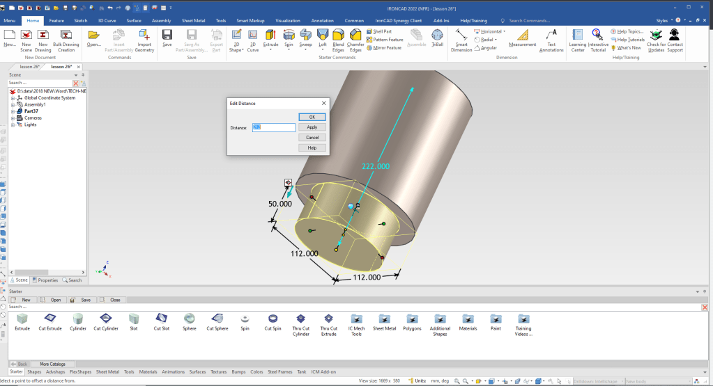
We drag and drop a cylinder the center of the existing cylinder and size it. IronCAD allows you to set the handles a specific distance from another feature. We will set it 212 mm form the top circular edge.
When you drag and drop it automatically recognizes corners, mid-points and centers.
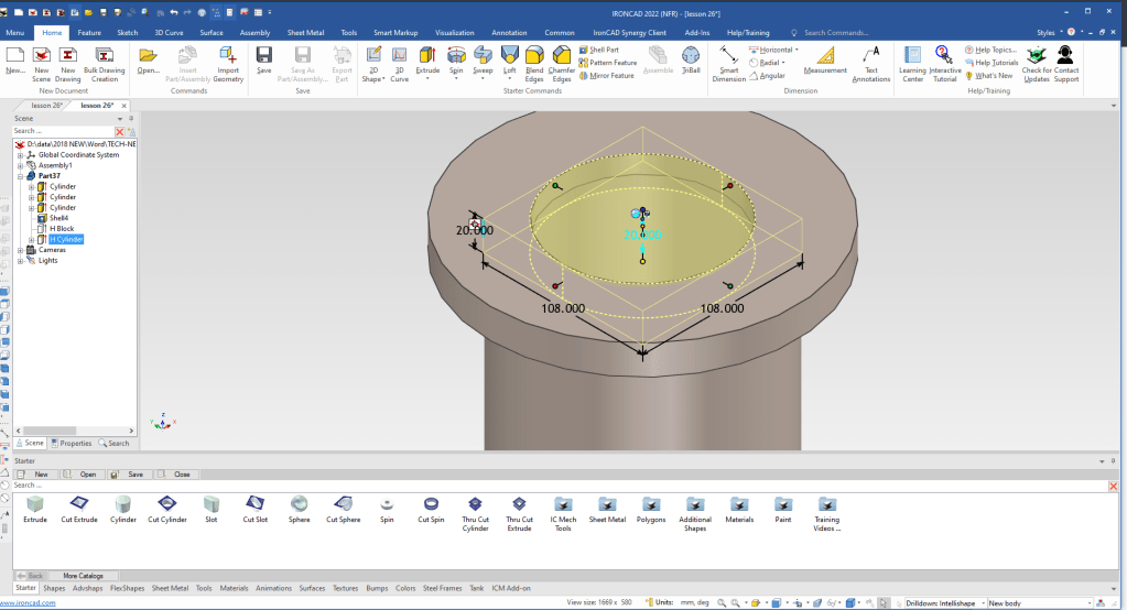
We now drag and drop a cylinder to the top center of the main cylinder create the top flange. It automatically set it to positive, we right and select “Flip Extrude Direction”, this saved feature manipulation.
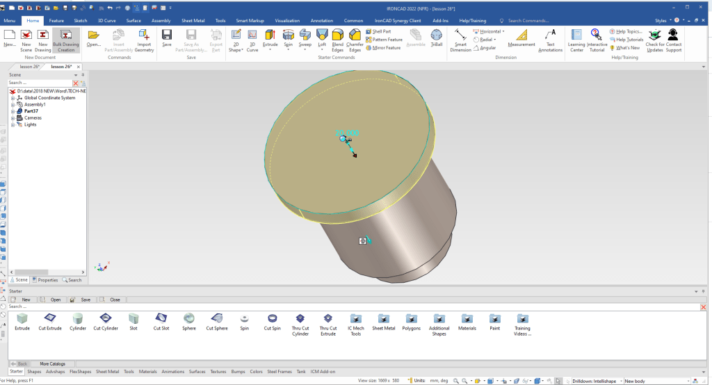
Most of your are use conventional constrained sketching and would not recognize that this shape at this level has consistent wall thickness. To an experiences “Feature Based” he realizes he can shell the shape, there by cutting much of the modeling time.
In this case will will define no open faces since there are other feature that will create them.

I will drag and drop a cut extrude to see the results of the shell. We will keep the cut extrude feature in the history to use in the future. We can just suppress with out altering the history. We usually drag it to the bottom of the history.

We suppress the cut extrude and drag and drop a cut cylinder to the center of the flange and size it.
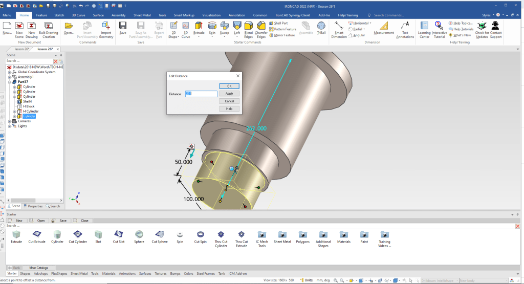
Now to add the the cylinder to the bottom. We drag and drop on the center of the bottom cylinder size it and locate the bottom by setting the bottom handle 251 mm from the center edge of the top flange.
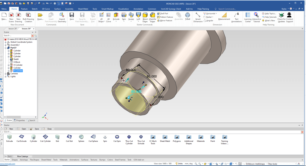
Now for the smaller hole in the bottom. We drag and drop a cut cylinder to the center of the bottom cylinder and size it. We don’t have to worry about the inner hole, it was created with the shell.
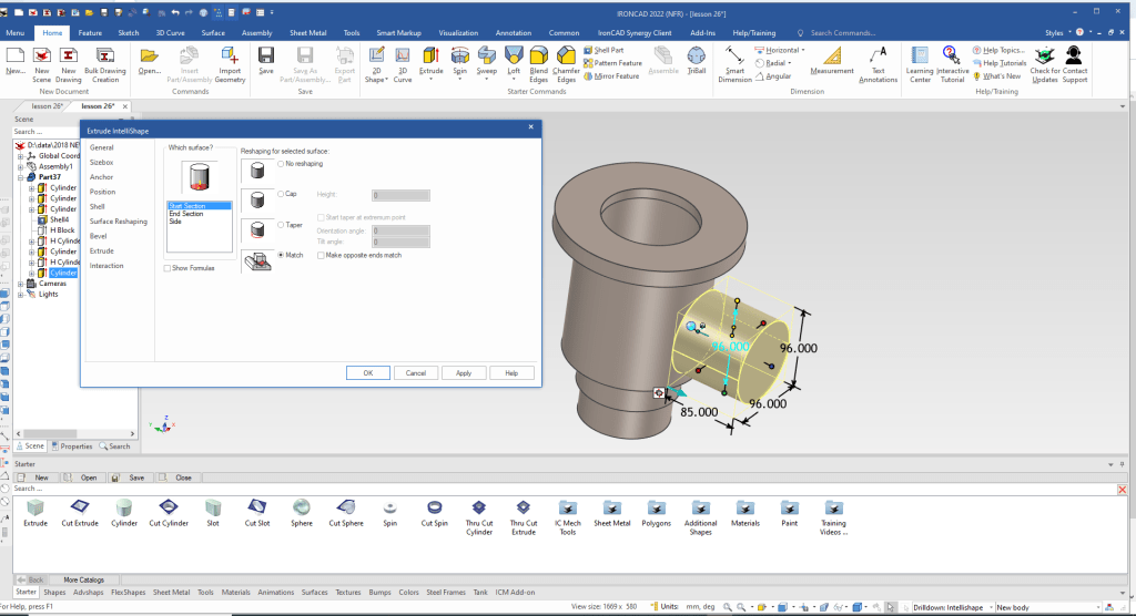
We drag and drop a cylinder to the main cylinder orient it, size and set the start to match the cylinder.
All of the features we use are based on sketches and have many feature that can be controlled. You can see the level of sophistication here.
IronCAD vs Solidworks Assembly Lesson 26 Lesson 2
We drag and drop a cylinder at the center of face of the horizontal locate and size it. eature, part and assembly manipulation tool. You can see the basics here:

IronCAD vs Solidworks Assembly Lesson 26 Lesson 2
I just notices I forgot the lower flange. No Problem. We will drag and drop a cylinder at the center of the bottom hole, size it and move the feature up in the history to the appropriate place.

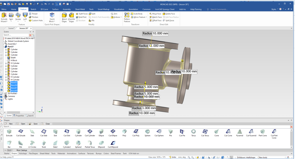
We add the blends
We are going create the ribs. IronCAD has two sketching options. The first are the wizards and the other is a standalone sketch.
The standalone offer much more flexibility in creating the features. It is used to bring in 2D graphics with dxf/dwg and you can use the graphics to create a 3D model.

We create the necessary graphics to create the ribs. We will not create the fillets here. I turn on the hide lines to aid in the create of the sketch.
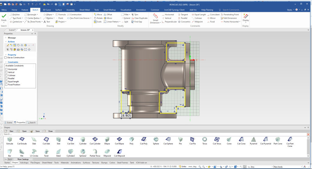
When say okay we have a standalone sketch just like the conventional systems and we can then create a solid with it. We will use the mid-plane options and select to add to the existing shape.

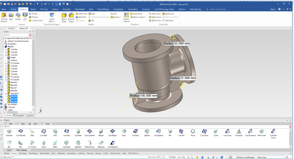
We select okay, now we have our ribs. We add the fillets.
Now we create the top threaded holes. We create the first one then using the Triball we create at linked pattern.

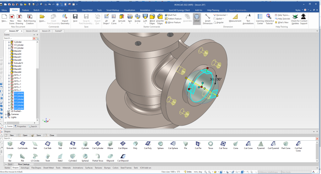
Now for the holes in the vertical flange. This time we don’t pattern them, we just copy link. I am just showing you the different features of the Triball. It is by far the most sophisticated feature, part, assembly manipulator available and offer huge option in design flexibility.
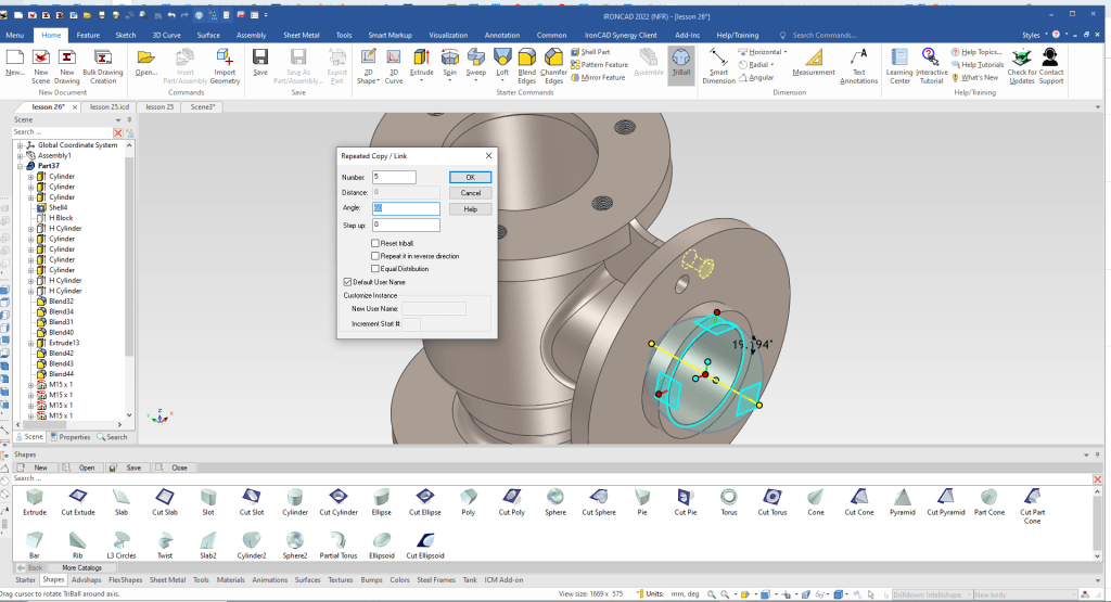
We now have to rotate them. We select all the holes and using the Triball we rotate them 30 degrees.
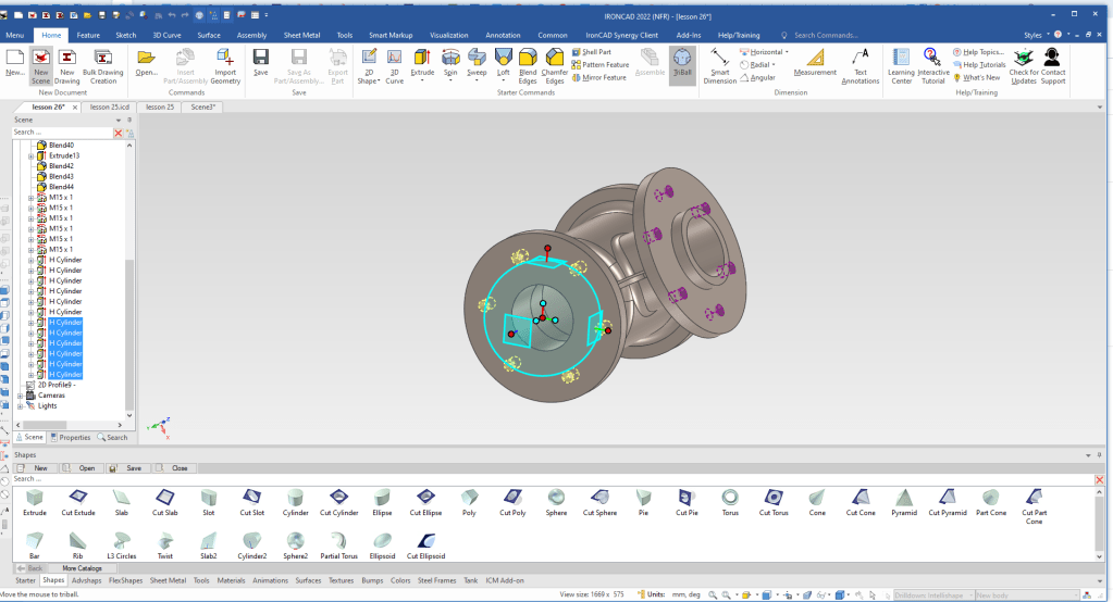
We will do a little trick we will copy link the existing holes to the bottom flange. With just a bit of manipulation with the Triball.
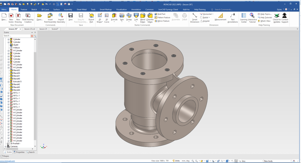
We are now done with the BODY. We hide the catalog for more workspace.
Please go to here to see the other lessons.
IronCAD vs Solidworks Assembly Lesson 26
It is very important that you look into how you or your engineers are creating the parts. Streamline Sketching and Feature Based Modeling is easy to learn and implement. It, alone, will increase productivity 10X. Now, IronCAD with its unique integrated history/direct edit functionality can increase your productivity another 5X or more with changes! Again, time is money in engineering.
More on Streamline Sketching and Feature Based Modeling.
3D Modeling Techniques Defined
To experience this increased level of productivity, please download IronCAD for a 30 day evaluation. Legacy data is no problem, IronCAD can read the native files of all of the popular programs. IronCAD is a great replacement for the subscription only Autodesk and PTC products.
For more information or to download IronCAD
Give me a call if you have any questions. I can set up a skype or gotomeeting to show this part or answer any of your questions on the operation of IronCAD. It truly is the very best conceptual 3D CAD system.
TECH-NET Engineering Services!
We sell and support IronCAD and ZW3D Products and
provide engineering services throughout the USA and Canada!
Why TECH-NET Sells IronCAD and ZW3D
If you are interested in adding professional hybrid modeling capabilities or looking for a new solution to increase your productivity, take some time to download a fully functional 30 day evaluation and play with these packages. Feel free to give me a call if you have any questions or would like an on-line presentation.
For more information or to download IronCAD or ZW3D
Joe Brouwer
206-842-0360
