Please go to here to see the other lessons.
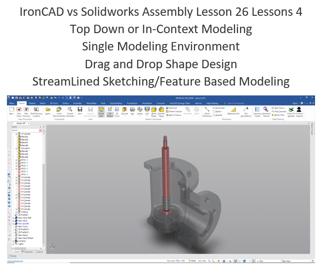
IronCAD vs Solidworks Assembly Lesson 26
What is the advantage designing with shapes?
Using shapes eliminates the need to create a sketch and extrude or revolve. If you created each feature individually it is easier to modify directly. Imagine a complex part. Give this concept a try today.
Design of Feed check Valve in Solidworks | Solidworks Exploded View
IronCAD vs Solidworks
While creating 3D models from drawing is the very best way to learn 3D CAD and maybe some design techniques is does not expose the designer to the design flexibility necessary in product design. IronCAD is all top down due to the single model environment. Creating mating parts is a cruise. But modeling is just one aspect of this well designed productive 3D CAD system.
I like to show step by step lessons So you can see the commands being used.
I always create the part before I watch the Video, so as to not taint my process. Of course, there are a multitude of ways to create a model. There is no right way, just more productive ways. From what I have seen from these very complicated processes done by the Solidworks Presenters, it is not just limited by the 3D CAD system.
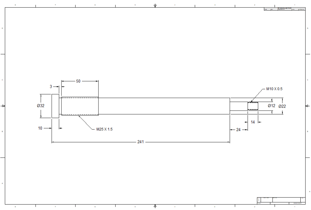
Here is the drawing if you would like to follow along.
For more information or to download IronCAD
We start with the Valve. We are doing top down or in context design. Which means we will using existing graphics to create our new part. We mostly use mating faces or edges.
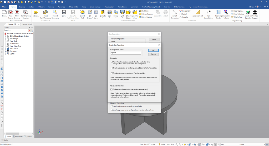
We will create a Spindle configuration. This is how you manage parts in a single model environment.
Note: Why does IronCAD call it a scene instead of a workspace? IronCAD was first released as a graphic design program called Trispectives. It still has much of the graphic design functionality. It truly is a wonderful mixture of professional 3D CAD and graphic design, which puts it in a much more flexible category as compared to the Pro/e (Creo) clones.
Also I have pinned the Catalog, you can autohide the catalog for more design space in the scene.
We open with the Valve to use as a reference to create the valve.
We pin the catalog open to show where we are dragging and dropping the shapes from. We usually set it to autohide to have more design real estate.
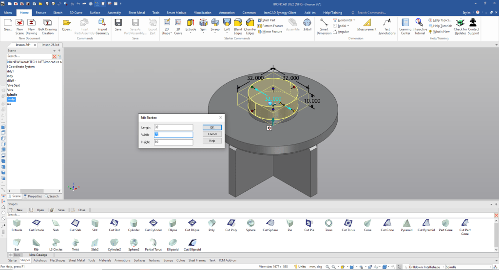
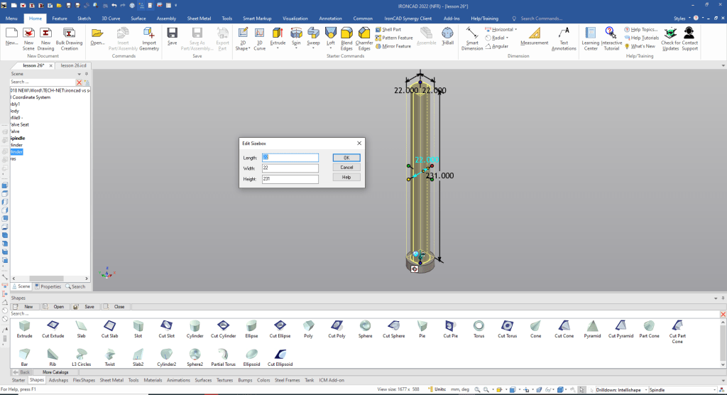
We drag and drop a cylinder on to a top facing using the right mouse button that allows us to create a new shape, creating a new part, the left button automatically makes it part of the existing shape. We can now name the new part.
We don’t need the Valve to create the part so we suppress it in this configuration.
We drag and drop a cylinder to the top center and size it.
For the threaded feature we just drag and drop a cylinder to the center of the top face and locate and size it with the handles. The handles have many options like locating from another features edge, midpoint, corner or center.
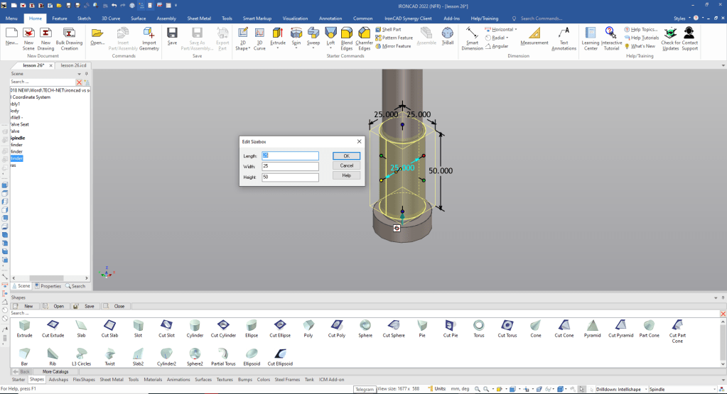
We add another cylinder to the center of the top face and size it.
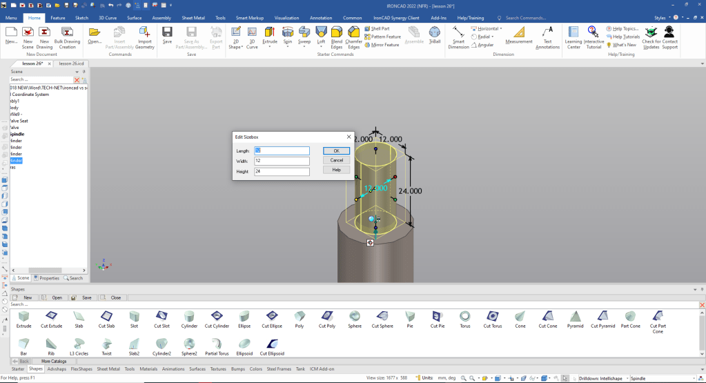
Now for the top threaded feature.

Now we just add cosmetic threads and we are done.

Please go to here to see the other lessons.
IronCAD vs Solidworks Assembly Lesson 26
It is very important that you look into how you or your engineers are creating the parts. Streamline Sketching and Feature Based Modeling is easy to learn and implement. It, alone, will increase productivity 10X. Now, IronCAD with its unique integrated history/direct edit functionality can increase your productivity another 5X or more with changes! Again, time is money in engineering.
More on Streamline Sketching and Feature Based Modeling.
3D Modeling Techniques Defined
To experience this increased level of productivity, please download IronCAD for a 30 day evaluation. Legacy data is no problem, IronCAD can read the native files of all of the popular programs. IronCAD is a great replacement for the subscription only Autodesk and PTC products.
For more information or to download IronCAD
Give me a call if you have any questions. I can set up a skype or gotomeeting to show this part or answer any of your questions on the operation of IronCAD. It truly is the very best conceptual 3D CAD system.
TECH-NET Engineering Services!
We sell and support IronCAD and ZW3D Products and
provide engineering services throughout the USA and Canada!
Why TECH-NET Sells IronCAD and ZW3D
If you are interested in adding professional hybrid modeling capabilities or looking for a new solution to increase your productivity, take some time to download a fully functional 30 day evaluation and play with these packages. Feel free to give me a call if you have any questions or would like an on-line presentation.
For more information or to download IronCAD or ZW3D
Joe Brouwer
206-842-0360
