3D Modeling Techniques Defined
Alternate Sheet Metal Modeling
No Sketching/Feature Based Modeling
The modeling technique is hugely responsible for the level of productivity. Those of you that are only trained in the sketch, sketch, constrain, constrain world are truly limited by not using the freedom of Streamlined Sketching and Feature Based Design, that is available in even the most Pro/e-ish of CAD systems. If your designers are designing in these very unproductive and time consuming processes it might be time to review your standard design processes. Don’t have any do you?
When I introduce IronCAD’s very flexible design paradigm I have a hard time to get the Pro/e clone users, like Solidworks and other programs to understand the drag and drop design paradigm.
Download IronCAD/Inovate and take the one day and 17 lesson course. I get rave reviews from my new customers. Give it a try, this is a fully functional 30 day evaluation with all of the native translators so you have access to your legacy engineering information.
IronCAD Self-Pace Training Course
I saw the following video challenge on linkedin and thought I would give it a try. I actually did it before I watched the video, so I did it a bit differently. This will give you an idea how different and flexible IronCAD is compared to the conventional Solidworks
Advanced Sheet metal Exercise in SolidWorks
Alternative Sheet Metal Design
I was introduced to 3D CAD in 1982 with Computervision CADDS 4, Found PC base 3D CADKEY at Boeing in 1986, Started using and selling it in 1987. This was 3D wireframe, no fancy sheet metal modules. We even had unfolding programs for the wire frame design.
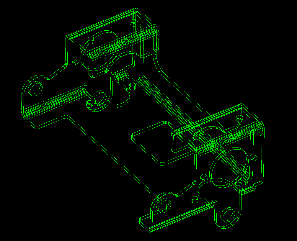
Here is an image of a this part in wireframe. With CADDS 4 we started with one color! Green on Black! They added Color for $35,000 per seat with CADDS 4X. I sold PC Based 3D CADKEY in 1987 with full color with 90% of the functionality of CADDS 4 and Catia 2 for $9000.00 with CADKEY, a 386 computer and 19in CRT. CADDS 4 and Catia were well over $100,000.00 per seat.
The 1980’s – 3D CAD – The Beginning
Are you looking up or down? This used to drive the engineers crazy. Yes, in those days 3D CAD was only in the realm of draftsmen!
Enter solid modeling in 1995. We started modeling our sheet metal like we do all of our models. I am afraid the many of the new millennial engineers really don’t know you can probably do your sheet metal design faster and easier than with the sheet metal modules. Now, I suppose if I only designed sheet metal parts it might be advantageous. But most of us design projects where a variety of mechanical design is used. Machining, sheet metal and other fabrication. So you may design just a few sheet metal parts.
Being a Boeing trained draftsman, I have extensive sheet metal design experience. We would do flat pattern development on undimensioned drawings to .005 tolerance. They would photograph them on to the tool.
Today, I just use the basic solid modeling tools. In IronCAD I may grab a feature from the sheet metal module, but that is it.
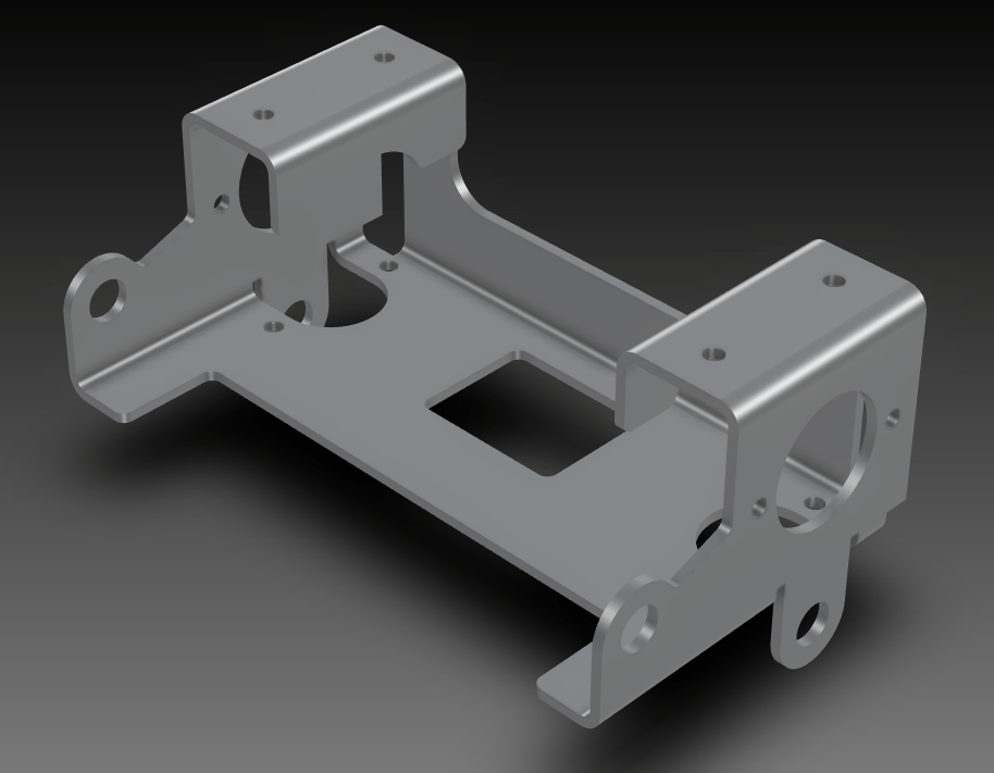
Here is just one of my many jobs.
IronCAD vs Solidworks
While creating 3D models from drawing is the very best way to learn 3D CAD and maybe some design techniques is does not expose the designer to the design flexibility necessary in product design. IronCAD is all top down due to the single model environment. Creating mating parts is a cruise. But modeling is just one aspect of a well designed productive 3D CAD system.
I would do a video, but I really am not good at it. So I will show you step by step. I will try and get IronCAD support to create one. They are very good.
I always create the part before I watch the Solidworks Video, so as to not taint my process. Of course, there are a multitude of ways to create a model. There is no right way, just more productive ways. From what I have seen from these very complicated processes done by the Solidworks presenter, it is not just limited by the 3D CAD system.
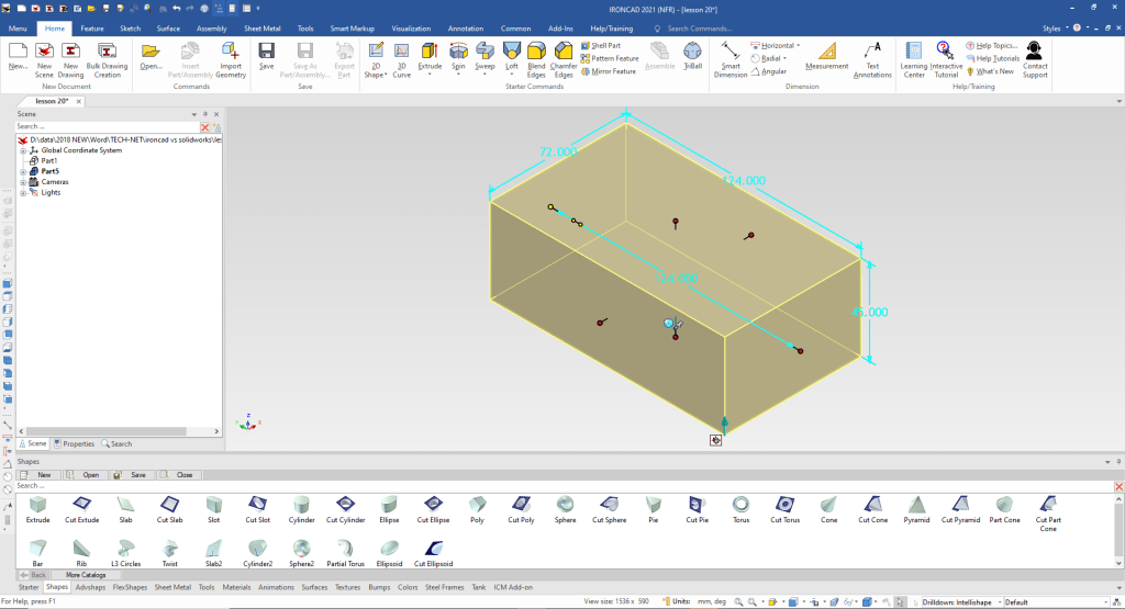
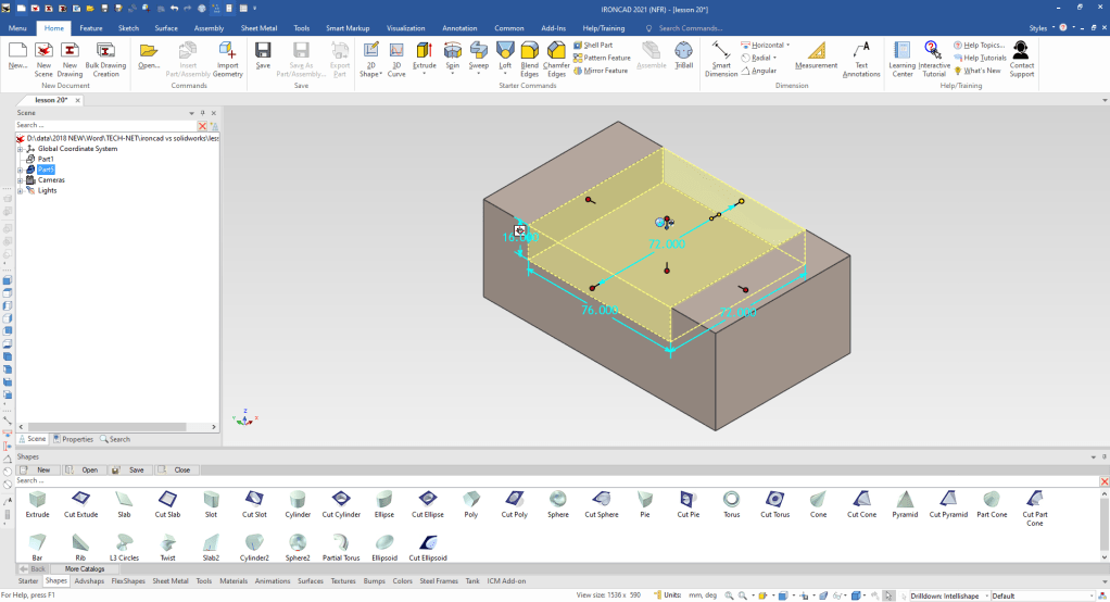
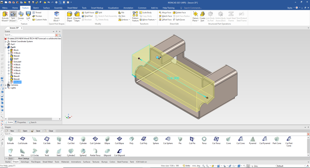
I drag and drop a block into the scene. I size it 124x72x45
Note: Why does IronCAD call it a scene instead of a workspace? IronCAD was first released as a graphic design program called Trispectives. It still has much of the graphic design functionality. It truly is a wonderful mixture of professional 3D CAD and graphic design, which puts it in a much more flexible category as compared to the Pro/e (Creo) clones.
I and drop a cut extrude to the mid-point of the top face of the existing block. I set the size to 76x72x16. There is a setting to size it symmetrical! You can pull the handle to match other features.
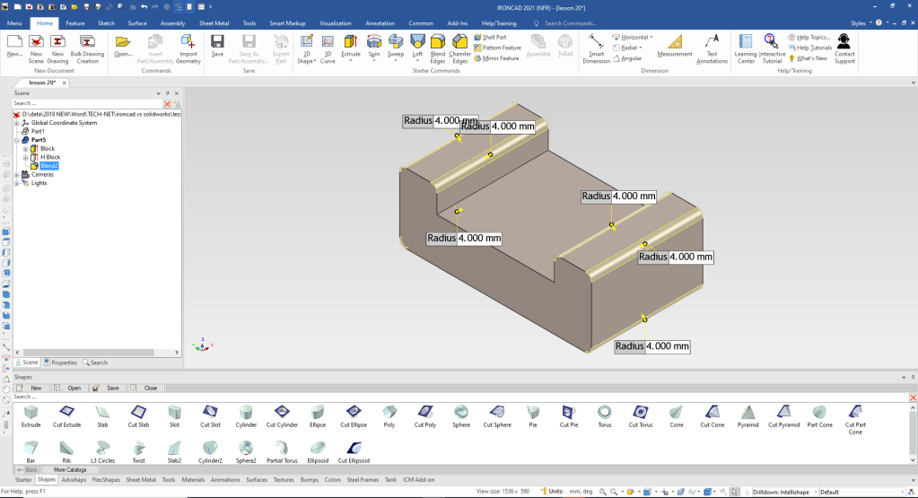
We create the fillets of 4 mm create the bends.
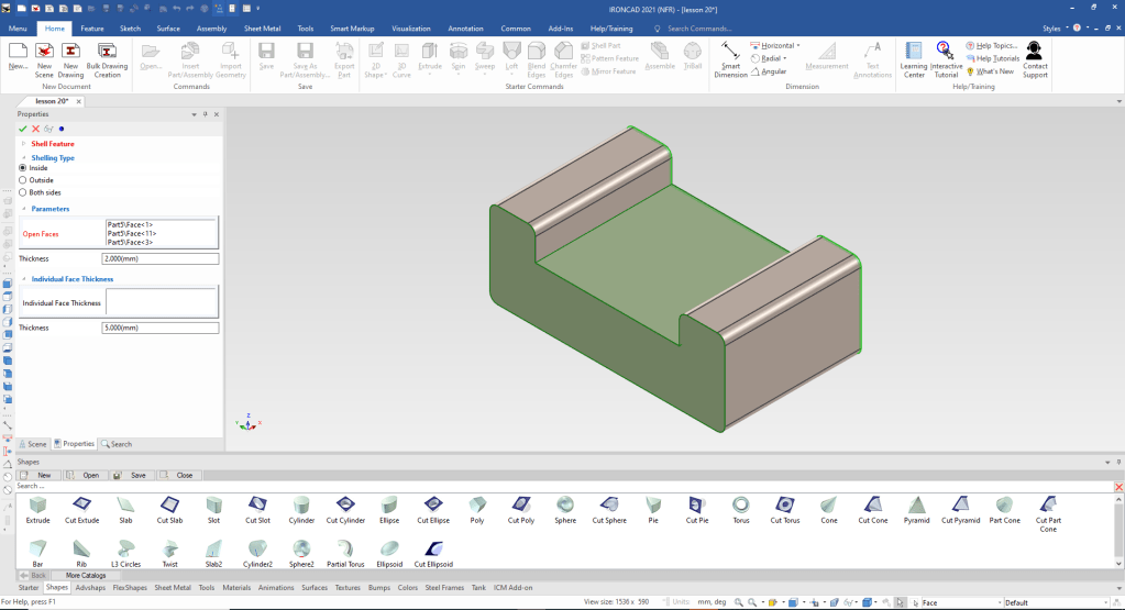
In design it is a bit different you basically make the solid shape to fit the requirement then define the sheet metal part with thin walls and adding and subtracting shapes.
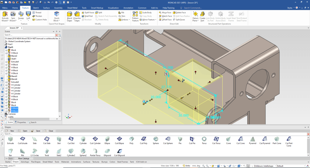
Now we just shell the necessary faces 2mm.
We can now start modifying the basics shape. Using the Extrude Wizard we create our plane. The Extrude Wizard automatically creates the extrusion when the sketch is complete.
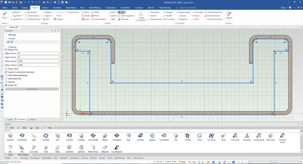
We set the depth to 2mm!

We drag and drop two small blocks and size them to create the corner.
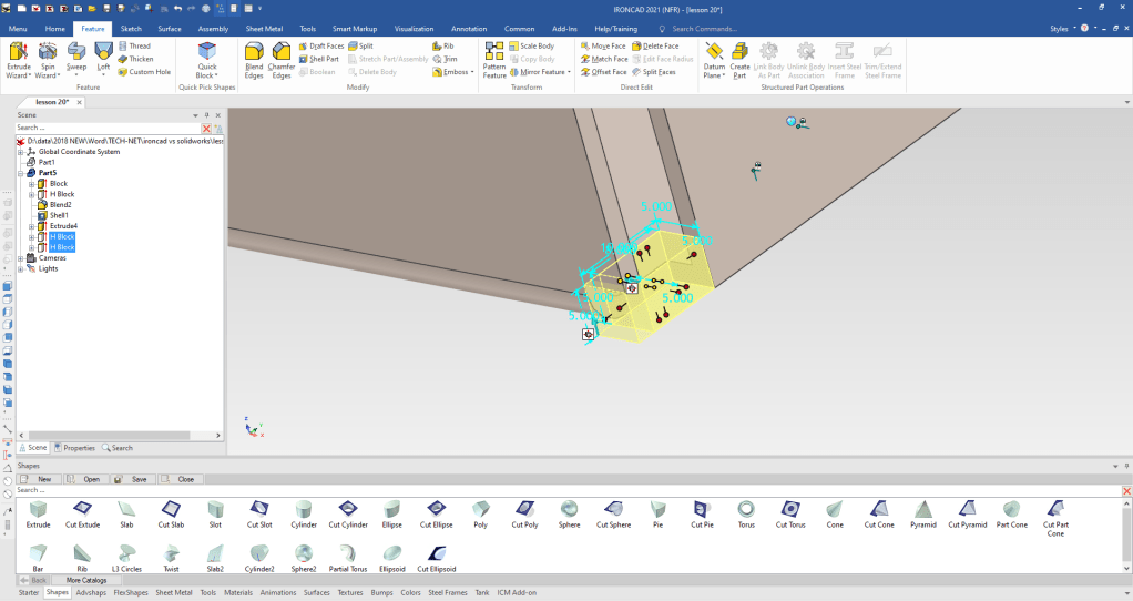
By pressing the spacebar the Triball can be moved to the midpoint of this edge to mirror link the features. You just reactivate the Triball by pressing the spacebar again.
linking is creating associated features.
We add our bends to the back face.
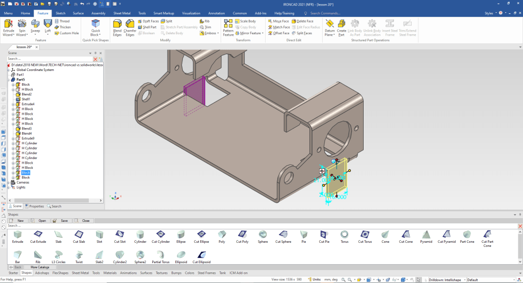
Now for our side cut. We again use the Extrude Wizard to create our sketching plane. i create the sketch I will add the blends later.
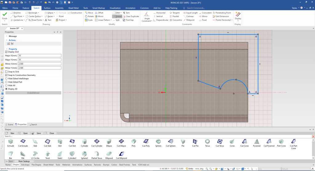
We select okay and pull the shape to fit.
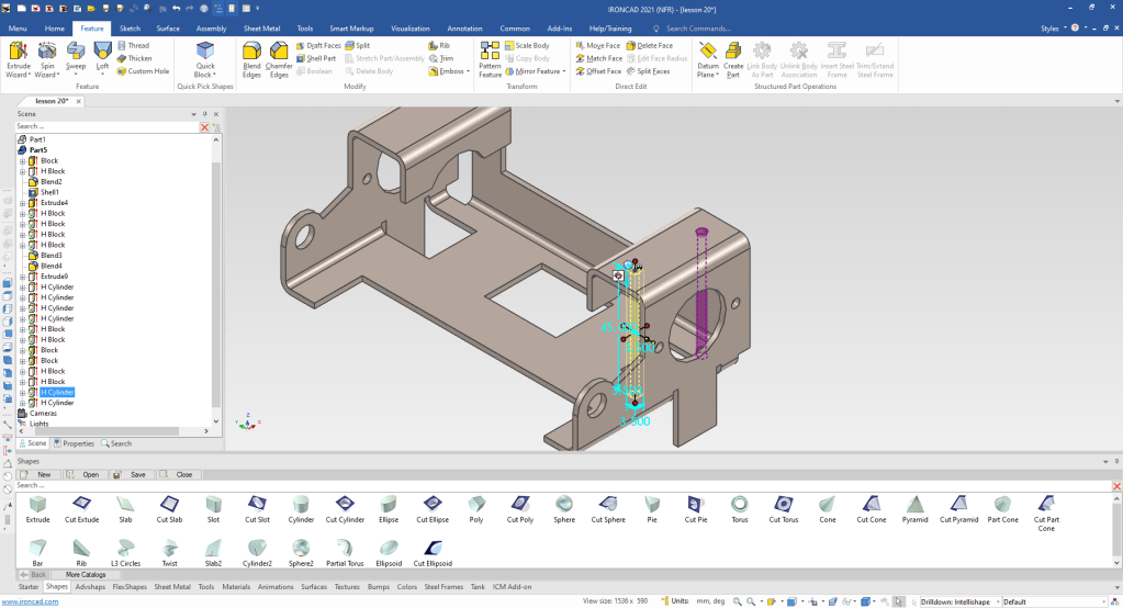
We drag and drop cut cylinders and locate and size them. The purple cylinder represents that it is a linked feature.
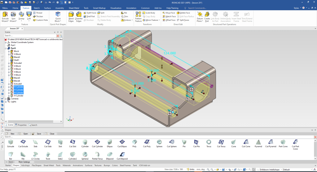
We drag and drop a cut extrusion for the tab. Locate it and size it! We use the Tribal to mirror link. You can see they are linked by the the linked feature in purple
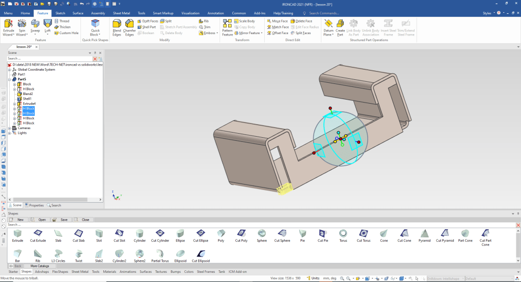
We create the tab by dragging and dropping a extrude to mid point and size it. We again use the Triball to mirror like the feature.
We just drag and drop the two extrudes to the bottom face locate and size them.
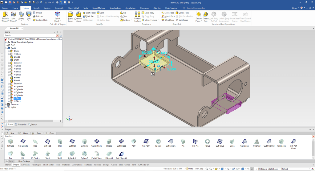
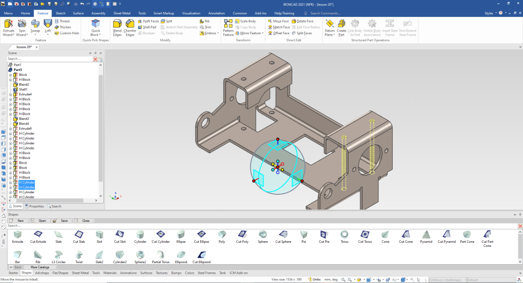
Now for the for holes on holes! We drag and drop one hole to the mid point of the face locate and size, then using the Triball we copy link the second hole.
We locate the Triball on the midpoint of the edge and mirror link the two holes. we have the most tedious part of this type of sheet metal adding the blends.
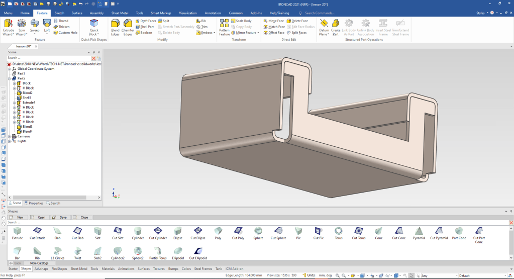
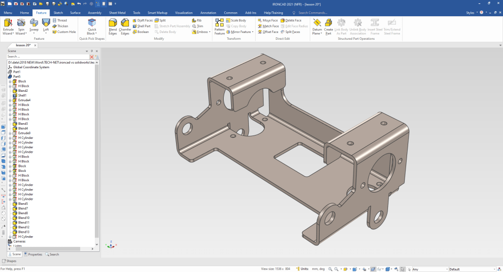
We are done with the basic modeling of the part. Now just to add the blends. Opps I missed the hole in the tab. Just drag and drop a cut cylinder to the center of the tab and pull to the other side.
You also can see I have autohid the catalog! You mostly works with it hidden for more scene real estate.
Now for the flat pattern. I sort of chuckled when I saw that the Solidworks presenter set the flat pattern to fold the major bends down. The problem with many modelers they are CAD jockeys not designers. To learn modeling only without the design intent or purpose does no favors for the budding design engineer. Most CAD is form, fit and function design and those should be a consideration on designing machine, sheet metal and fabrications.
IronCAD can turn any correctly designed sheet metal model into a flat pattern. It is especially beneficial when working with imported or non-native dumb models.
IronCAD can convert the correctly designed sheet metal model native or imported to a sheet metal model that will create an associated flat pattern. But we won’t do that in this lesson since it really doesn’t add much. If you change it you can just unfold it again.
You do not dimension a flat pattern, you just want to make sure you can get a full size .dxf to the sheet metal shop.
I do not recommend doing flat patterns unless you make them in house. I suggest you send them the 3D model and fully detailed AID. Most sheet metal shops like to have the fully defined documentation along with the model. But I will not do that here, because we are only going to create a undimensioned flat pattern.
I never supply a flat pattern to my sheet metal shop. We want the the part to match the defined model and documentation.
I am going to the my original part, I want want to add the flat pattern to the existing AID as a new sheet.
I select the unfold command set the sheet metal thickness and select the bottom face. It selects all the relative bends and faces affected.
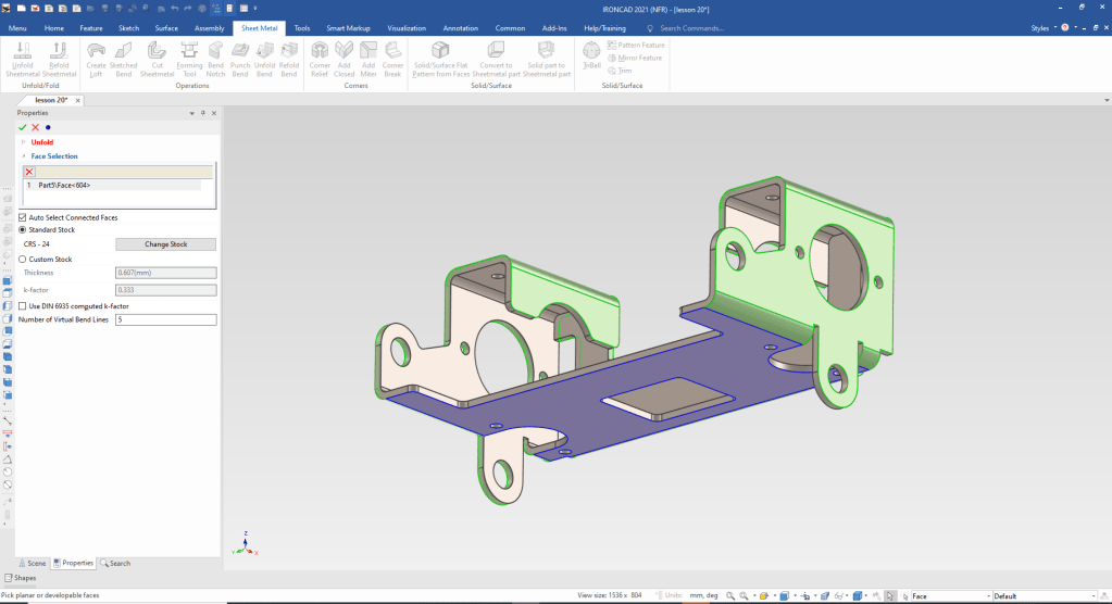
We select okay and we have our flat pattern.
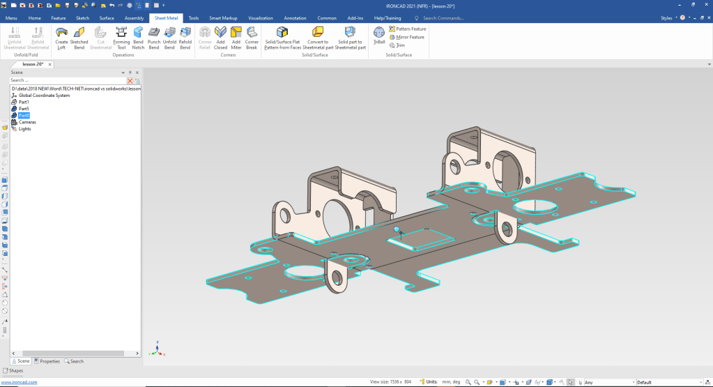
Both the part and then flat pattern a in the same file so we will create a flat pattern configuration to create our AID (drawing). This flat pattern is not associated to the part like the using the sheet metal function. But if you are working with dumb non-native imported parts this is fine.
IronCAD is a SME (Single Model Environment), you define the different scenes with parts and assemblies with configurations.
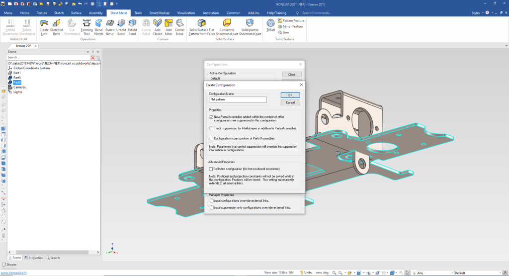
Here is the flat pattern in it own configuration.
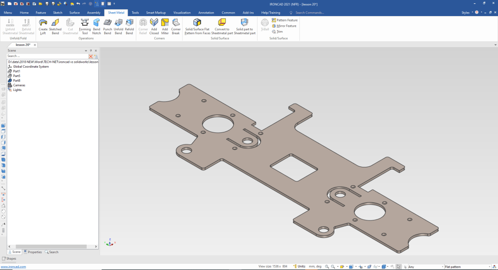
While Isometric AIDs are a bit easier to understand, they leave much to be desired to truly define the part. I expect all engineering professionals to be able to understand a drawing, if you can’t you will be out the door.
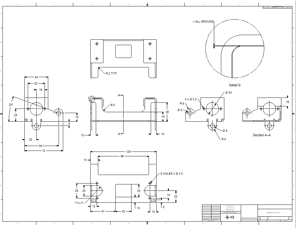
Now we will detail the part correctly. Of course, we cannot really detail a part by itself. We need to have the assembly so we can define relationships of the features so both or more mating parts align. So I will just defined the part so it can be understood by manufacturing and those that may want to create the model.
When converting drawings to 3D you have to re-detail the part to assure it is the same as the drawing.
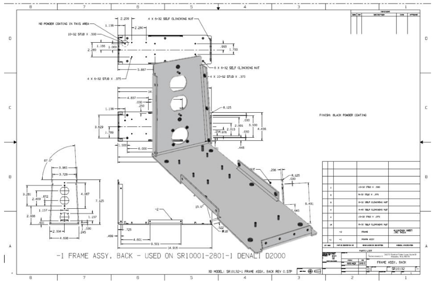
Here is the AID. IronCAD has a separate documentation module. It is impossible to correctly detail a part without the mating parts. This is detailed so you can create the 3D model!
All You Wanted to Know About Drawing to 3D Conversions
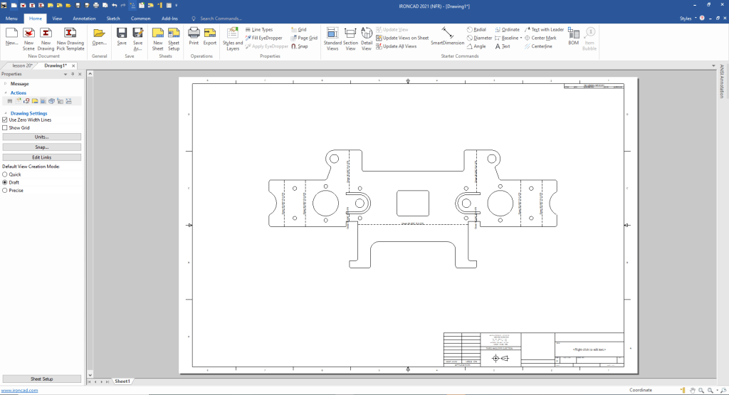
Unless you are working in a sheet metal house you should send the AID (drawing) and the 3D model to the sheet metal supplier to create the flat pattern. But IronCAD will unfold any correctly designed imported model.
Here is the AID of the flat pattern full scale so we can get a .dxf to send to the sheet metal house. No we do not dimension flat patterns. The detailed AID will provide all of the necessary final tolerances.
So there you go. That is how we modeled sheet metal parts in the past and I still do.
Here are a few more sheet metal lessons!
IronCAD vs Fusion 360 Lesson 16
IronCAD vs Fusion 360 Lesson 17
IronCAD vs Solidworks Lesson 16
It is very important that you look into how you or your engineers are creating the parts. Streamline Sketching and Feature Based Modeling is easy to learn and implement. It, alone, will increase productivity 10X. Now, IronCAD with its unique integrated history/direct edit functionality can increase your productivity another 5X or more with changes! Again, time is money in engineering.
More on Streamline Sketching and Feature Based Modeling.
3D Modeling Techniques Defined
To experience this increased level of productivity, please download IronCAD for a 30 day evaluation. Legacy data is no problem, IronCAD can read the native files of all of the popular programs. IronCAD is a great replacement for the subscription only Autodesk and PTC products.
For more information or to download IronCAD
Give me a call if you have any questions. I can set up a skype or gotomeeting to show this part or answer any of your questions on the operation of IronCAD. It truly is the very best conceptual 3D CAD system.
TECH-NET Engineering Services!
We sell and support IronCAD and ZW3D Products and
provide engineering services throughout the USA and Canada!
Why TECH-NET Sells IronCAD and ZW3D
If you are interested in adding professional hybrid modeling capabilities or looking for a new solution to increase your productivity, take some time to download a fully functional 30 day evaluation and play with these packages. Feel free to give me a call if you have any questions or would like an on-line presentation.
For more information or to download IronCAD or ZW3D
Joe Brouwer
206-842-0360
