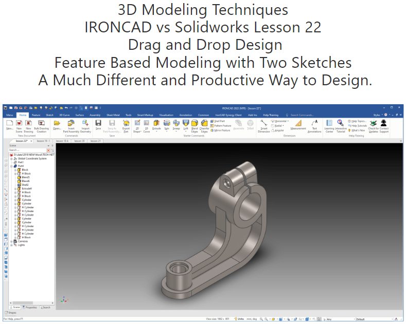
What is the advantage designing with shapes?
Using shapes eliminates the need to create a sketch and extrude. The above part has 14 shapes and 2 sketches. This is a simple part and we have eliminated 14 constrained sketches and 14 extrusions. Imagine a complex part. Give this concept a try today.
Sketches in IronCAD are an integrated part of the shape. You can have standalone sketches for use creating other features.
The modeling technique is hugely responsible for the level of productivity. Those of you that are only trained in the sketch, sketch, constrain, constrain world are truly limited by not using the freedom of Streamlined Sketching and Feature Based Design, that is available in even the most Pro/e-ish of CAD systems. If your designers are designing in these very unproductive and time consuming processes it might be time to review your standard design processes. Don’t have any do you?
When I introduce IronCAD’s very flexible design paradigm I have a hard time to get the Pro/e clone users, like Solidworks and other programs to understand the drag and drop design paradigm.
Download IronCAD/Inovate and take the one day and 17 lesson course. I get rave reviews from my new customers. Give it a try, this is a fully functional 30 day evaluation with all of the native translators so you have access to your legacy engineering information.
The below link will give 6 short introduction to unique IronCAD operations.
I saw the following video challenge on linkedin and thought I would give it a try. I actually did it before I watched the video, so I did it a bit differently. This will give you an idea how different and flexible IronCAD is compared to the conventional Solidworks
SolidWorks tutorial for beginners exercise 131
IronCAD vs Solidworks
While creating 3D models from drawing is the very best way to learn 3D CAD and maybe some design techniques is does not expose the designer to the design flexibility necessary in product design. IronCAD is all top down due to the single model environment. Creating mating parts is a cruise. But modeling is just one aspect of a well designed productive 3D CAD system.
I would do a video, but I really am not good at it. So I will show you step by step. I will try and get IronCAD support to create one. They are very good.
I always create the part before I watch the Solidworks Video, so as to not taint my process. Of course, there are a multitude of ways to create a model. There is no right way, just more productive ways. From what I have seen from these very complicated processes done by the Solidworks Presenters, it is not just limited by the 3D CAD system.
Here is the drawing if you would like to follow along.
For more information or to download IronCAD
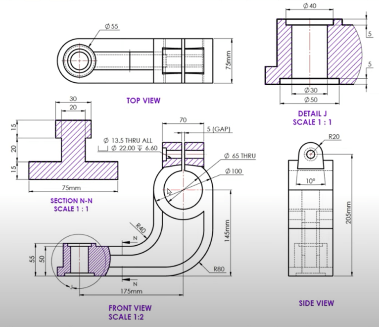
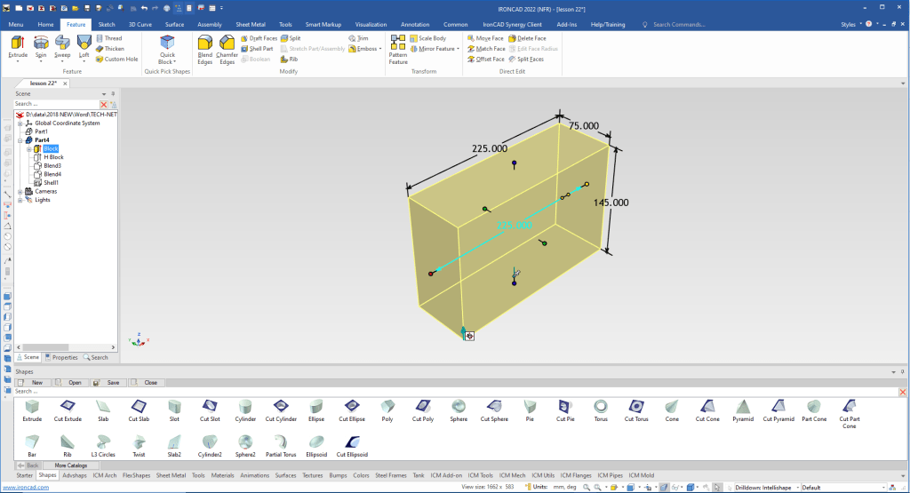
I drag and drop a extrude block into the scene. I size it 225x75x145
Note: Why does IronCAD call it a scene instead of a workspace? IronCAD was first released as a graphic design program called Trispectives. It still has much of the graphic design functionality. It truly is a wonderful mixture of professional 3D CAD and graphic design, which puts it in a much more flexible category as compared to the Pro/e (Creo) clones.
Also I have pinned the Catalog, you can autohide the catalog for more design space in the scene.
I and drop another cut extrude locate and size it. We use the “Edit Distance From Point” option when you right click a handle so as not to need to do calculations.

We add the two blends.

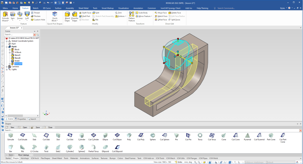
We now drag and drop an extrude block locate and size it. You can see the block inside the shape, no problem you can always select in the scene browser for modification.

We now will used the Extrude Wizard to create the 20 mm web. It sets up a sketch plane and you can set the depth of the extrusion. Eliminating the extrude step. If you haven’t notice there are no defined planes in the scene browser or history.
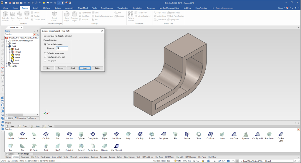
It takes us to the sketch. We now just select the edges we want to project.
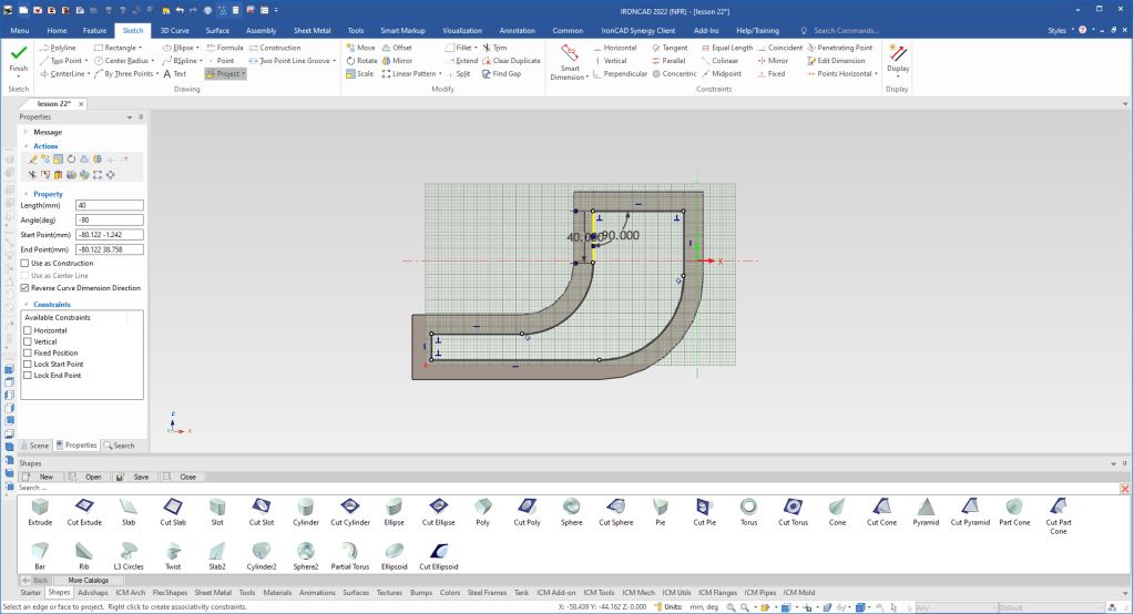
We select okay and we have our web. Using the Triball, we locate the Triball to the mid-point of the web and the to the mid-point of the relative feature.
Triball Demo 1
The top rib is thinner so we will drag and drop a cut extrude and locate it.
We select the new feature, turn off the Triball by depressing the spacebar and move to a point we want to mirror. We will copy link so both are affected when we make a change. You can see that the related feature shows as purple.
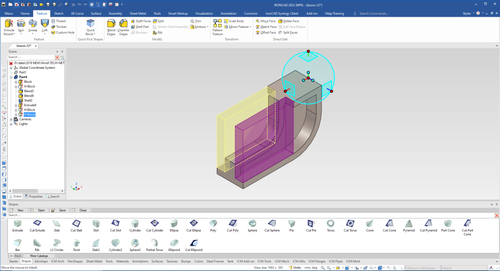
We drag and drop the cylinder to the the base of the model using the mid-point of the edge and pull the handle to match the relevant edge.
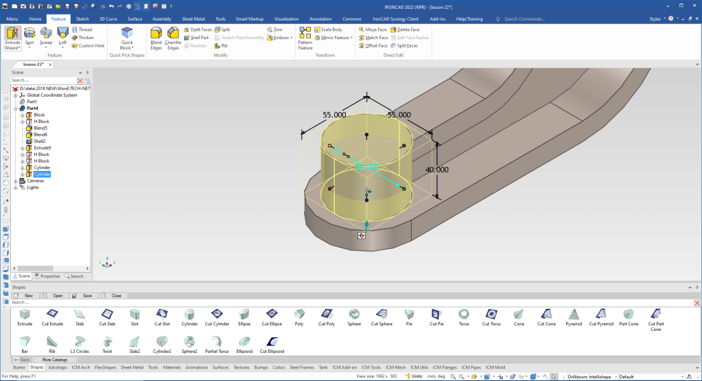
We drag and drop a cylinder using the of the rib. We size the cylinder then set the height from the bottom.
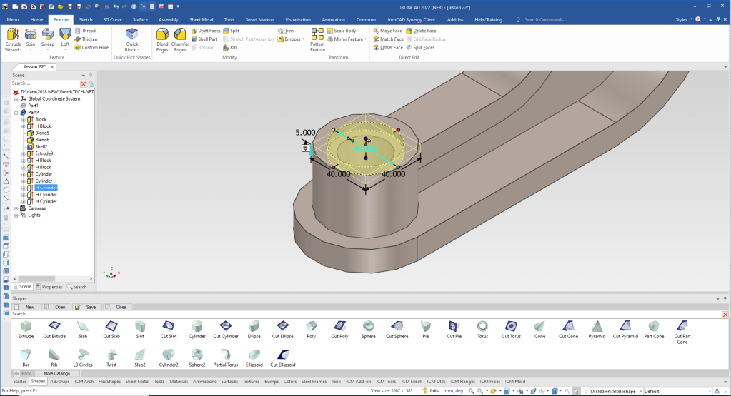
We again drag and drop the three cut cylinders to the center of the boss and size them to create the counterbored and thru holes.
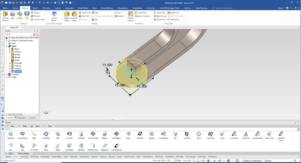
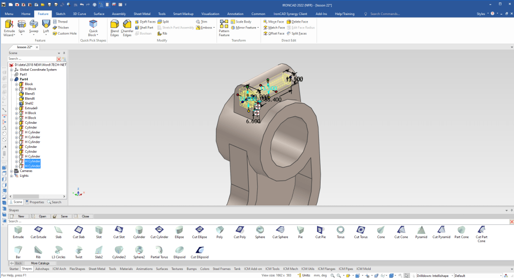
We drag and drop a cylinder to the front face, locate and size it.
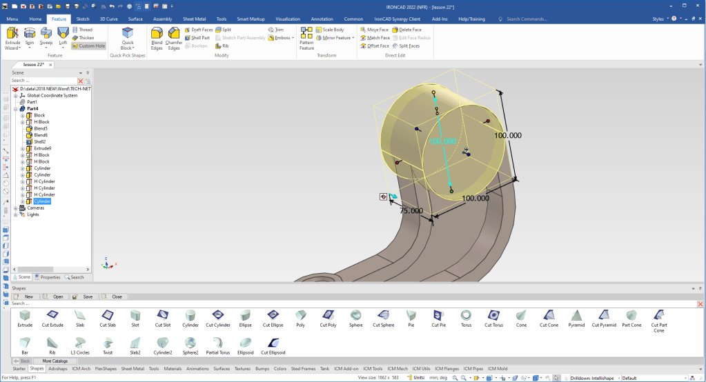
We drag and drop a cylinder to the face of the model and locate and size it.

The shapes we are dragging and dropping are called intellishapes and all are based on sketches. We will now edit the shape of our new cylinder by selecting “Edit Cross Section”.
Learning IronCAD! Lesson 4
IronCAD Intellishape Deconstructed
What are we Dragging and Dropping?
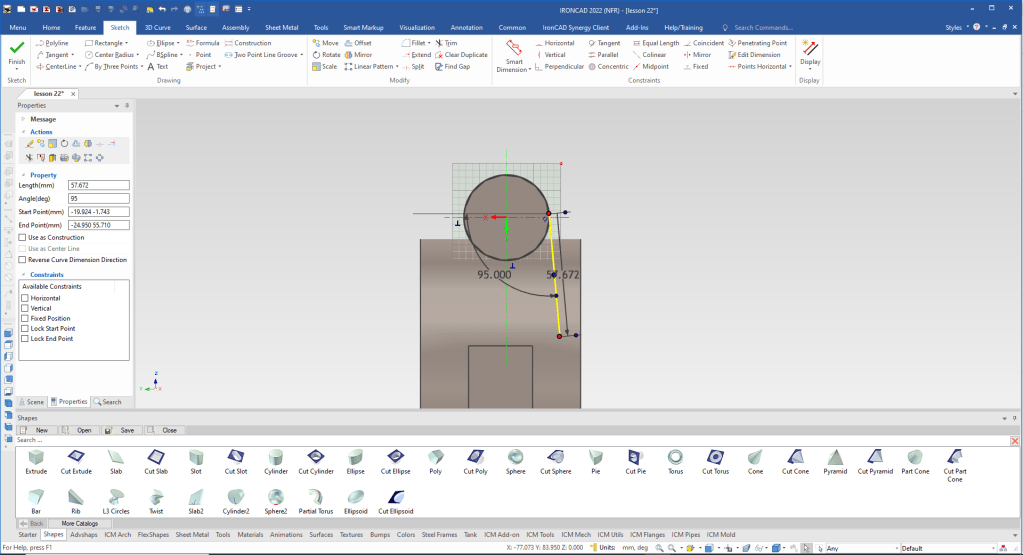
We will use tangent line and actually set the angle as we create the line.
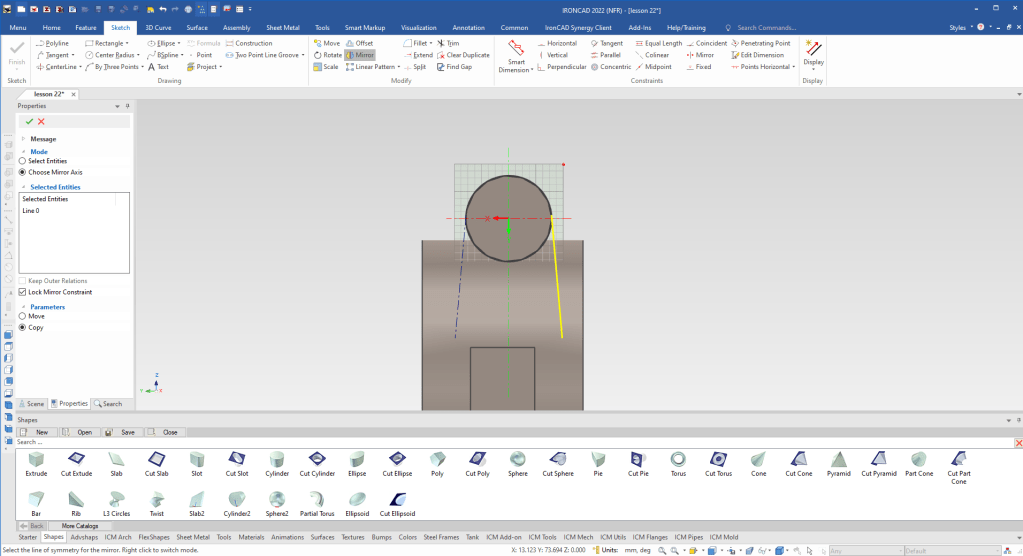
We mirror copy the line.
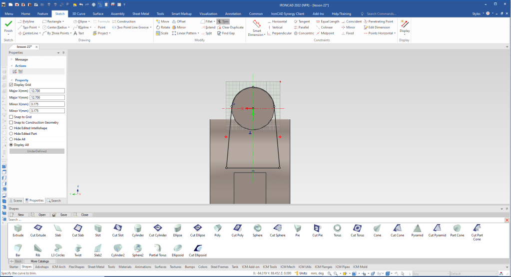
We create the bottom line and trim the circle, we know we have a good sketch by the white dot on the end of the entities, there would be red dots shown indicating a problem.
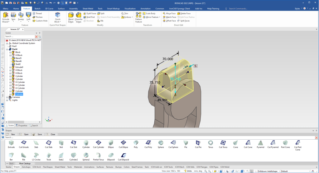
When we say okay you can see we now have the correct feature.
We drag and drop a cut cylinder to the center of the boss creating the hole. We size it.

We drag and drop cut cylinder to create the counterbore and thru hole.
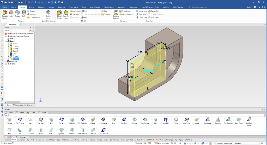
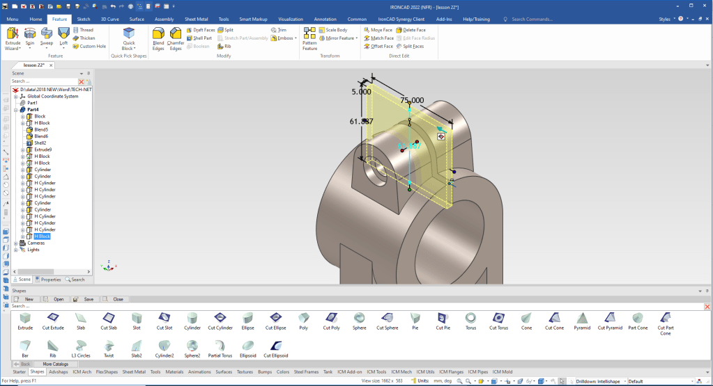
We drag and drop a cut extrude to create the final feature. Locate and size it. We can set the handles to symmetry to lower the modeling steps.
We are now done with the part. Only two sketches, one nothing but projecting some edges and the other, editing an intellishape.
It is very important that you look into how you or your engineers are creating the parts. Streamline Sketching and Feature Based Modeling is easy to learn and implement. It, alone, will increase productivity 10X. Now, IronCAD with its unique integrated history/direct edit functionality can increase your productivity another 5X or more with changes! Again, time is money in engineering.
More on Streamline Sketching and Feature Based Modeling.
3D Modeling Techniques Defined
To experience this increased level of productivity, please download IronCAD for a 30 day evaluation. Legacy data is no problem, IronCAD can read the native files of all of the popular programs. IronCAD is a great replacement for the subscription only Autodesk and PTC products.
For more information or to download IronCAD
Give me a call if you have any questions. I can set up a skype or gotomeeting to show this part or answer any of your questions on the operation of IronCAD. It truly is the very best conceptual 3D CAD system.
TECH-NET Engineering Services!
We sell and support IronCAD and ZW3D Products and
provide engineering services throughout the USA and Canada!
Why TECH-NET Sells IronCAD and ZW3D
If you are interested in adding professional hybrid modeling capabilities or looking for a new solution to increase your productivity, take some time to download a fully functional 30 day evaluation and play with these packages. Feel free to give me a call if you have any questions or would like an on-line presentation.
For more information or to download IronCAD or ZW3D
Joe Brouwer
206-842-0360
