What is the advantage designing with shapes?
Using shapes eliminates the need to create a sketch and extrude. Sketches in IronCAD are an integrated part of the shape. You can have standalone sketches for use creating other features.
The modeling technique is hugely responsible for the level of productivity. Those of you that are only trained in the sketch, sketch, constrain, constrain world are truly limited by not using the freedom of Streamlined Sketching and Feature Based Design, that is available in even the most Pro/e-ish of CAD systems. If your designers are designing in these very unproductive and time consuming processes it might be time to review your standard design processes. Don’t have any do you?
When I introduce IronCAD’s very flexible design paradigm I have a hard time to get the Pro/e clone users, like Solidworks and other programs to understand the drag and drop design paradigm.
Download IronCAD/Inovate and take the one day and 17 lesson course. I get rave reviews from my new customers. Give it a try, this is a fully functional 30 day evaluation with all of the native translators so you have access to your legacy engineering information.
The below link will give 6 short introduction to unique IronCAD operations.
I saw the following video challenge on linkedin and thought I would give it a try. I actually did it before I watched the video, so I did it a bit differently. This will give you an idea how different and flexible IronCAD is compared to the conventional Solidworks
SolidWorks tutorial for beginners exercise 158
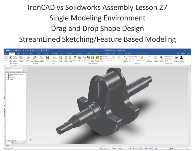
IronCAD vs Solidworks
While creating 3D models from drawing is the very best way to learn 3D CAD and maybe some design techniques is does not expose the designer to the design flexibility necessary in product design. IronCAD is all top down due to the single model environment. Creating mating parts is a cruise. But modeling is just one aspect of a well designed productive 3D CAD system.
I would do a video, but I really am not good at it. So I will show you step by step. I will try and get IronCAD support to create one. They are very good.
I always create the part before I watch the Solidworks Video, so as to not taint my process. Of course, there are a multitude of ways to create a model. There is no right way, just more productive ways. From what I have seen from these very complicated processes done by the Solidworks Presenters, it is not just limited by the 3D CAD system.
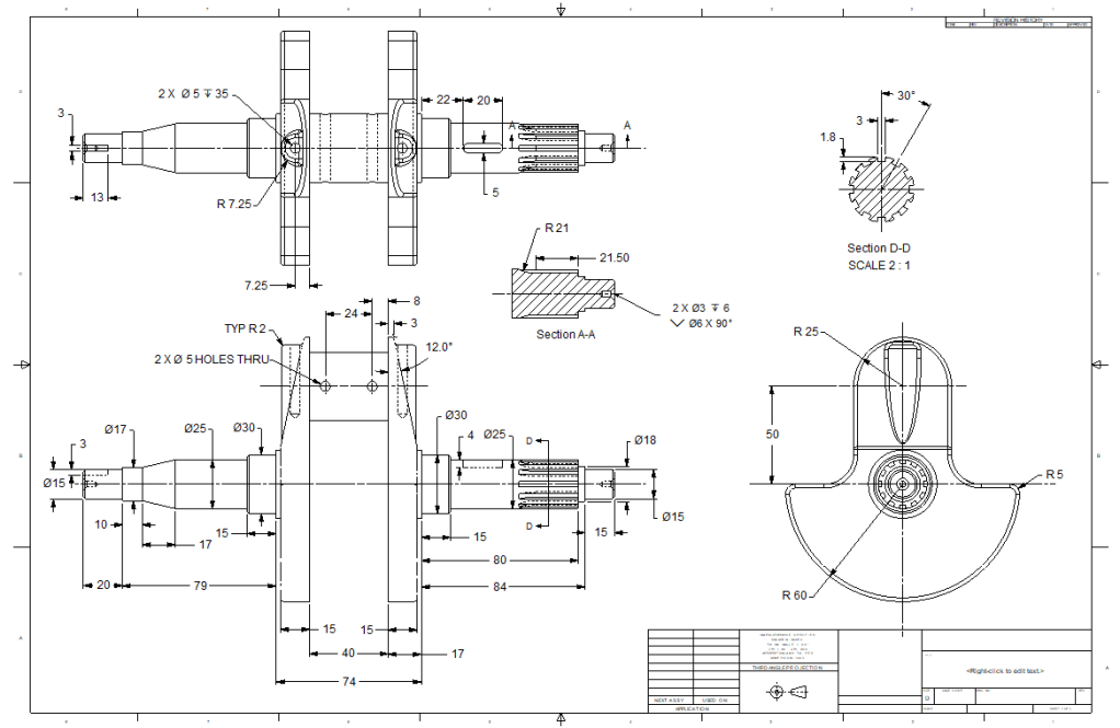
Here is the drawing if you would like to follow along.
You must make an AID (Drawing) every time you create a model from a drawing and check it.
For more information or to download IronCAD
We set our units to millimeters.
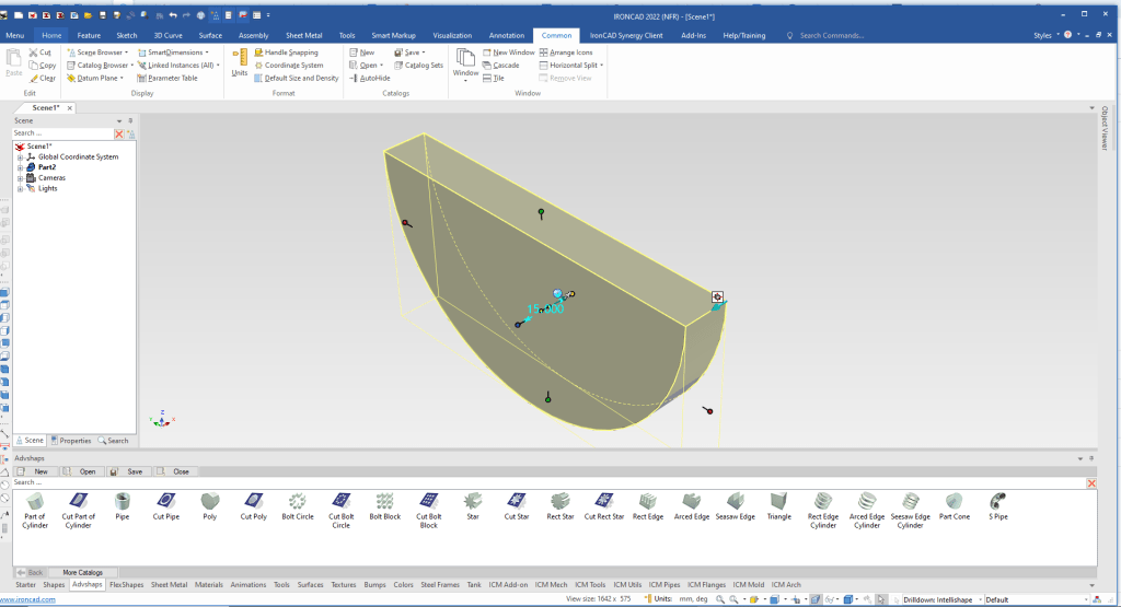
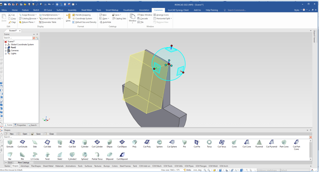
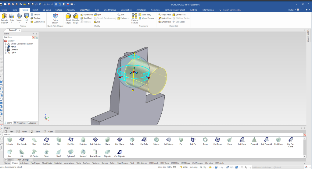
We will start by dragging and dropping a “Part of a Cylinder” from the “Advshape” catalog into the scene, orient it with the Triball and size it.
As soon as you drag and drop a shape on to the scene it instantly creates a new part. We are looking at the intellishape, which make up the part. We will rename the part.
Note: Why does IronCAD call it a scene instead of a workspace? IronCAD was first released as a graphic design program called Trispectives. It still has much of the graphic design functionality. It truly is a wonderful mixture of professional 3D CAD and graphic design, which puts it in a much more flexible category as compared to the Pro/e (Creo) clones.
Also I have pinned the Catalog, you can autohide the catalog for more design space in the scene.
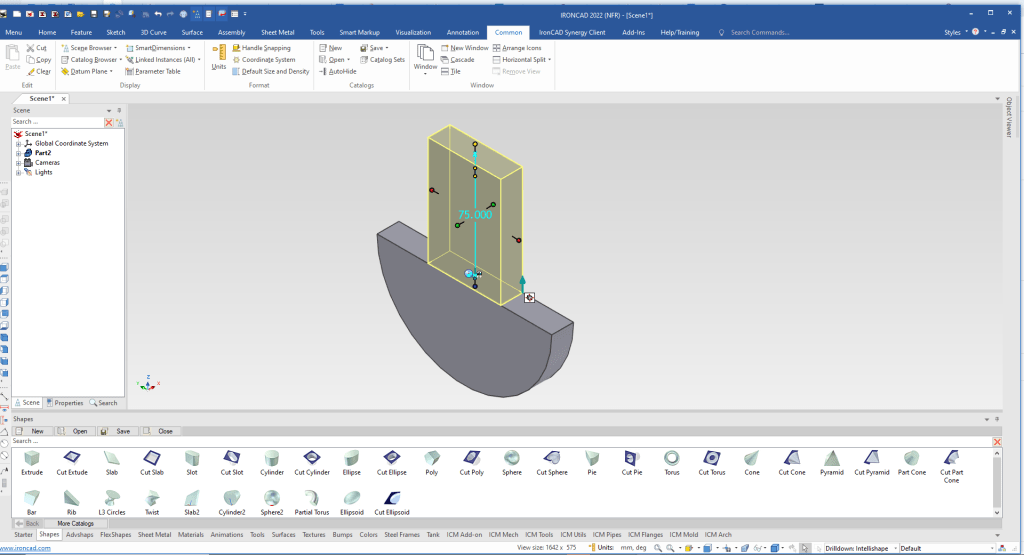
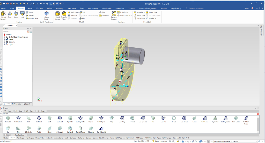
I will drag and drop extrude to the midpoint of the rectangle and size it. The handles on the size box have options. If I pull the side handle with the right mouse button it pulls the shape symmetrical, and with the left button just affects the handle we are pulling.
I size it by using the calculation 135-60!
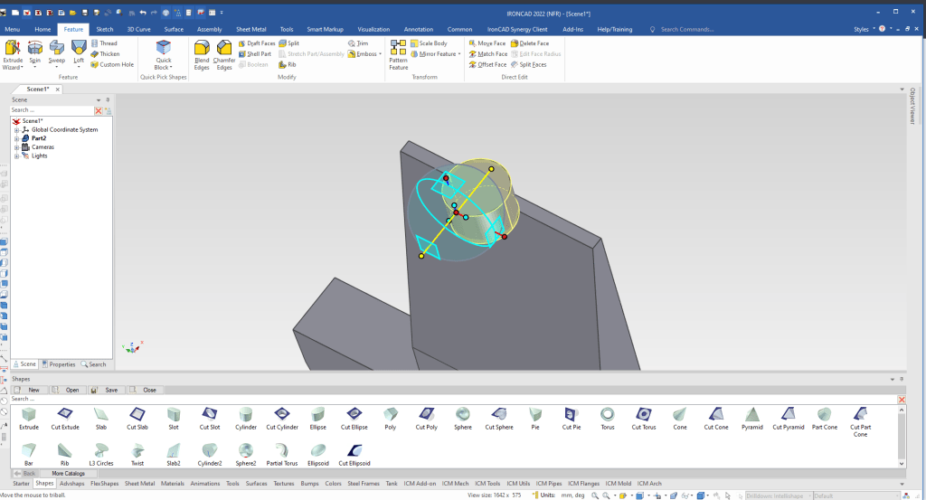
We drag and drop a cut extrude to the center of the front top edge, size it and with the Triball we rotate it.
We orient the existing shape so we are looking down on the part. When dragging and dropping feature they drop on depending on how the shape is oriented. We drop it on the midpoint of the backtop edge, size it and locate it with the Triball. We move the Triball only by using the spacebar to the front quadrant. We than can use the option “Edit distance from point”.
We then use the handles to push/pull it to the correct size.
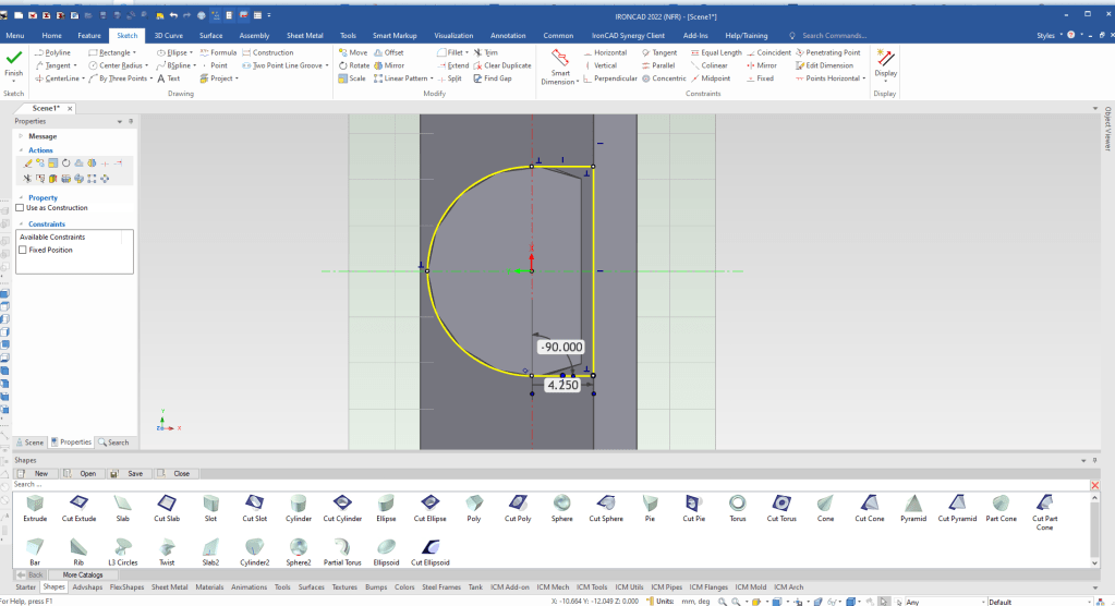
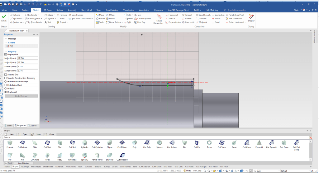
The Intellishape is based on sketches. We right click the Intellishape and select “Edit Cross section. This brings up a sketch and we do the appropriate changes. We orient the sketch if needed.
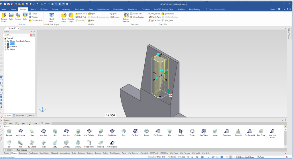
We select okay and we are done with one of the cranks. We will now add the offset shaft. We drag and drop a cylinder on midpoint of the top edge, size it and using the Tribal to locate it.
We select the feature we want to mirror copy.
We now move the Tribal to the center of the cylinder by using selecting the middle red dot and using the “point to point” option with a right click and picking the center of the cylinder and the opposite edges.
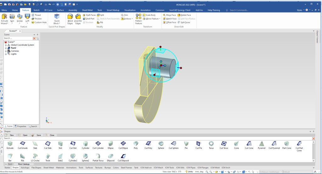
We select the inside handle that defines the mirror direction and select “Mirror Link”
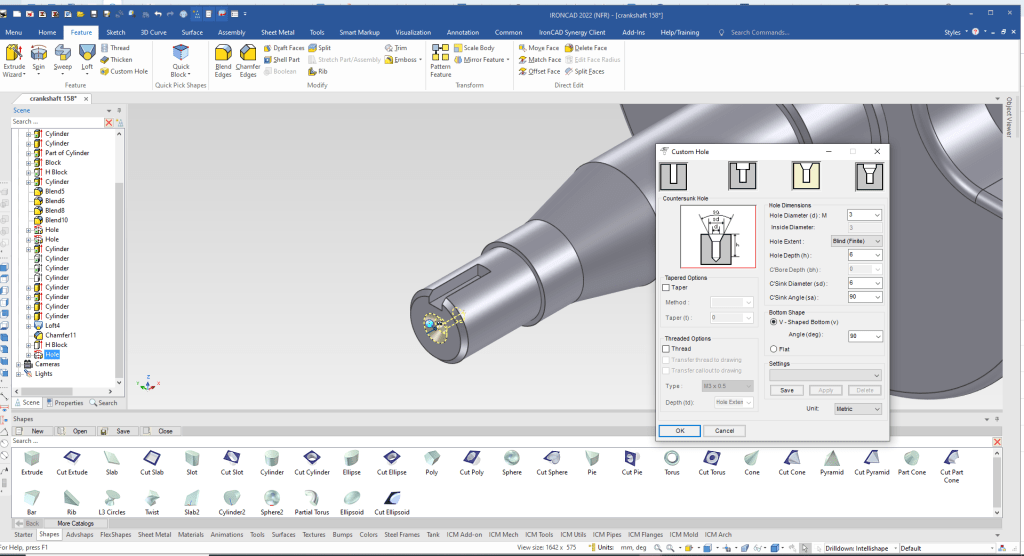
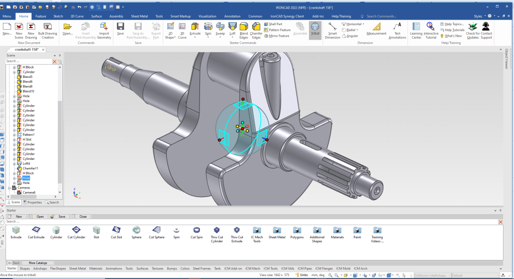
We will use the tools catalog and select custom hole. We will size it but make the depth 40 to make up for the blend. We will move it with the Triball.
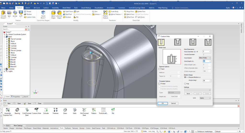
We will use the Tribal to raise it 5mm then copy it link it for the other side.
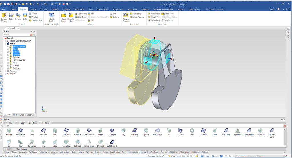
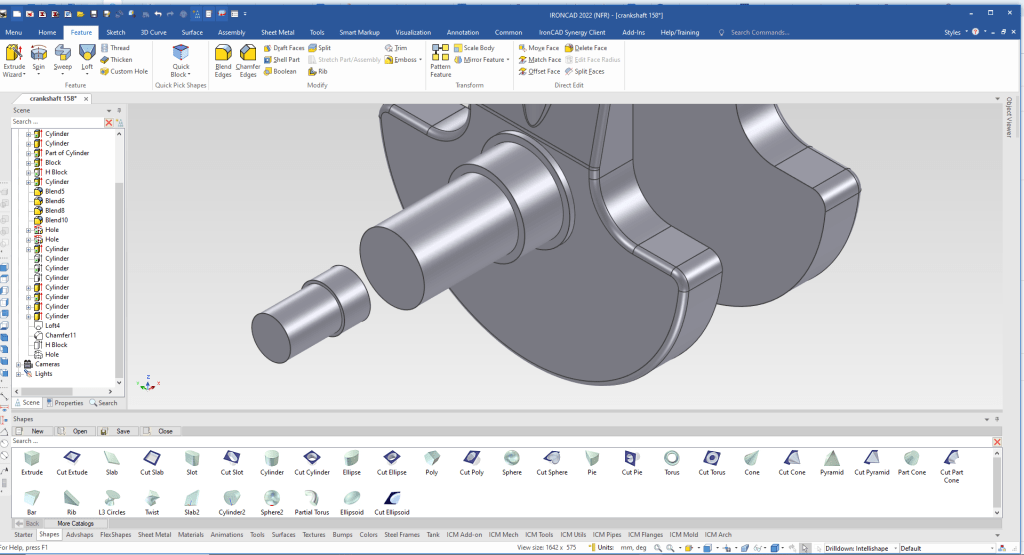
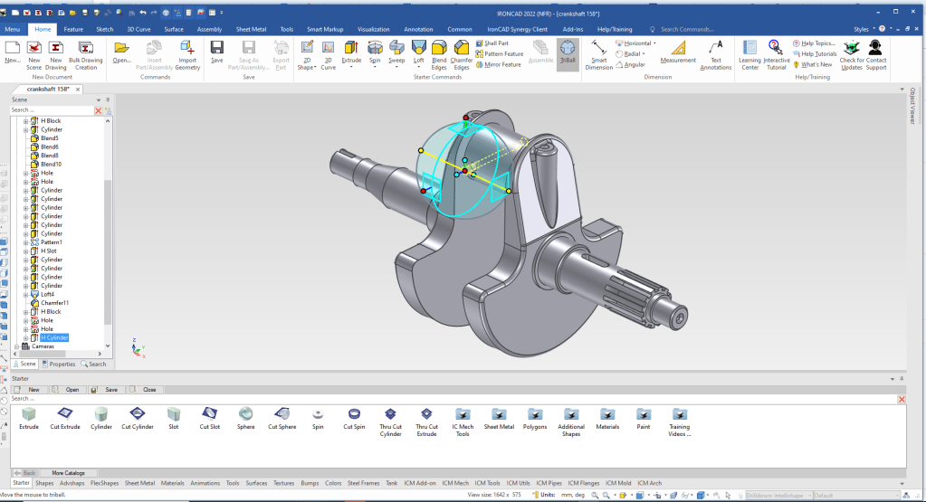
We are now done with the crank portion. We drag and drop the two cylinders, locate and size them.
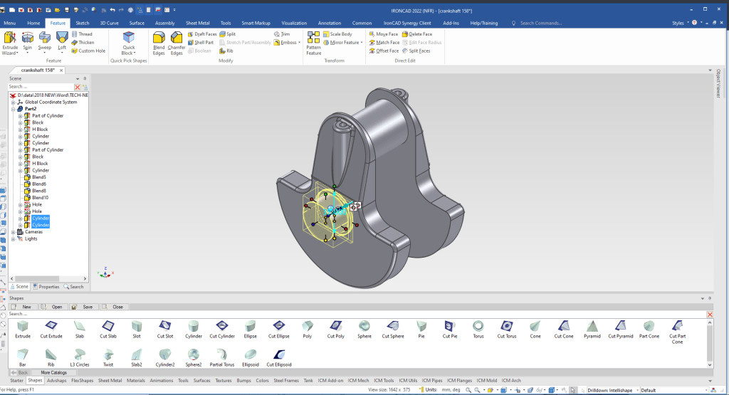
We realize the new cylinders can be mirrored linked. We turn on the Triball, locate it and mirror link the two cylinders. Linking allows you to change either one of the features and the other automatically changes.
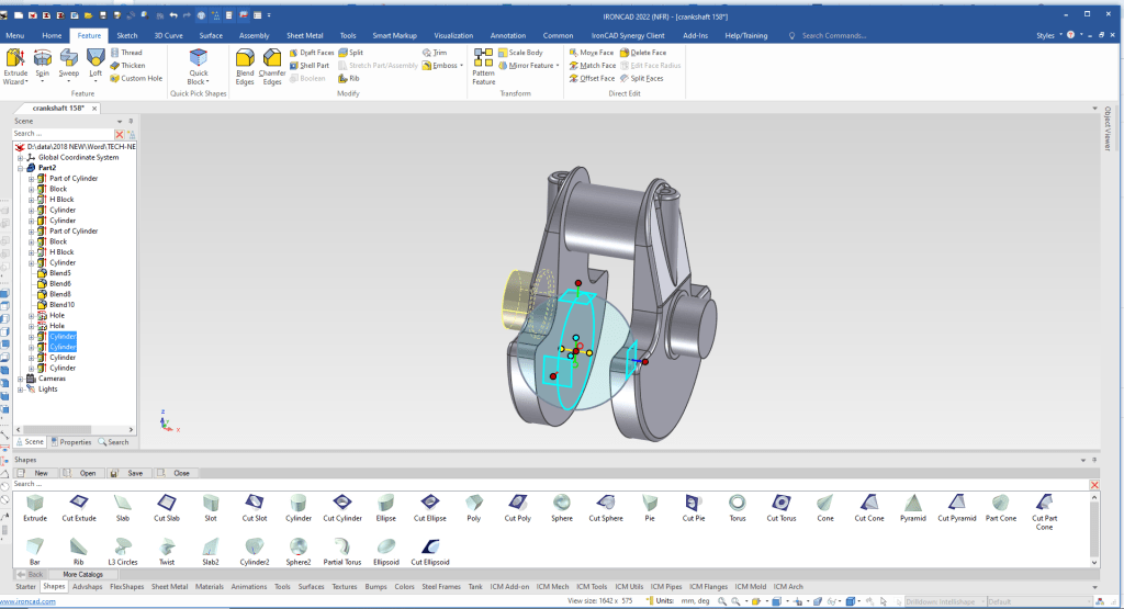
Now we will drag and drop the cylinders on the near side. You can see left a space.
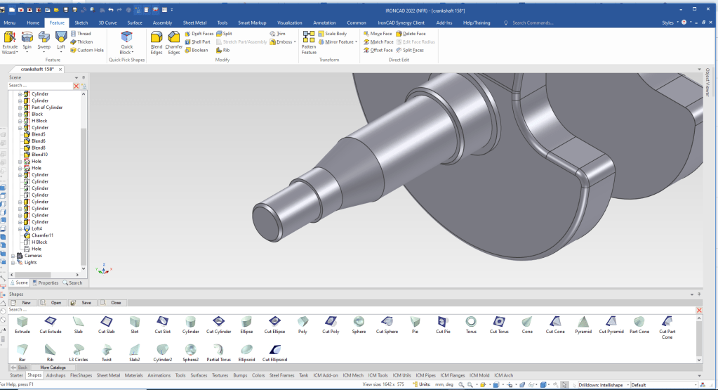
now we will create a loft to fill the gap. We just select the two faces.
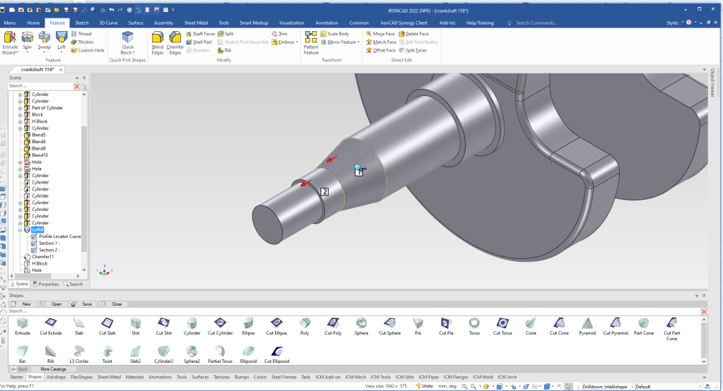
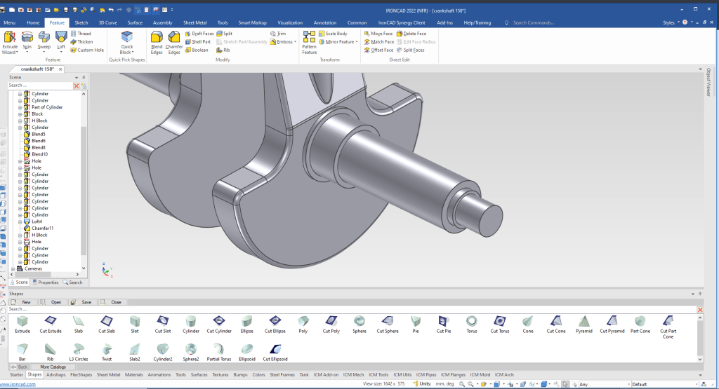
We just add the chamfers.
We drag and drop a cut extrude to the center of the cylinder and size it.
We select the tool catalog and select custom hole and set the size.
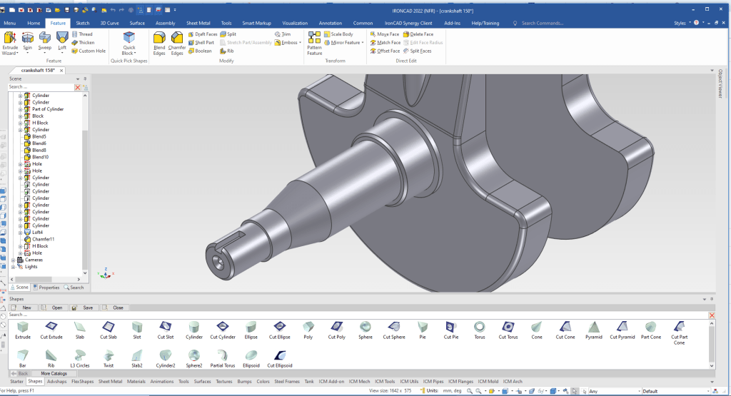
We are done with the near side.
Now for the far side. We drag and drop the 3 cylinders, locate and size them.
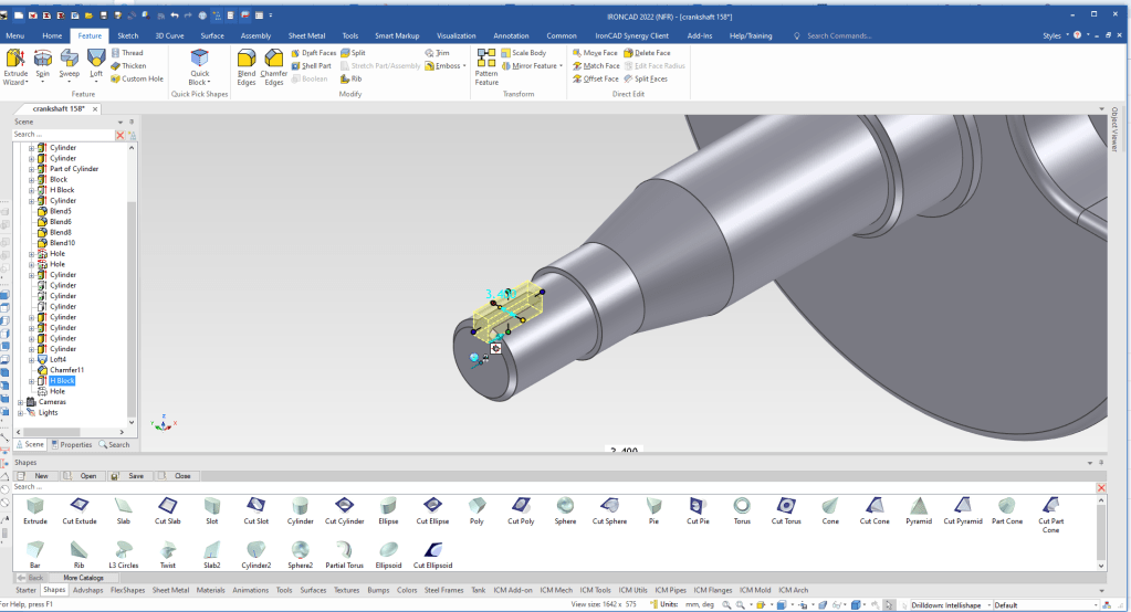
Now for the splines. We drag and drop a cut block on the face of the cylinder, we have to use the Triball to rotate it since we will have to edit the cross section of the shape.
Now we will edit the shape by select “edit cross section”
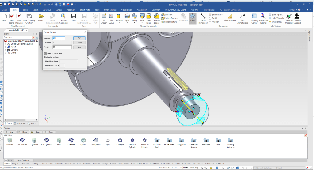
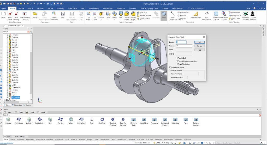
We will use the the Triball and rotated copy link the groove.
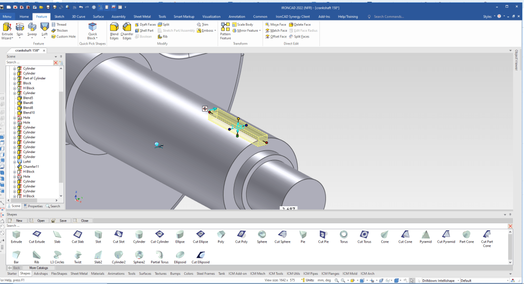
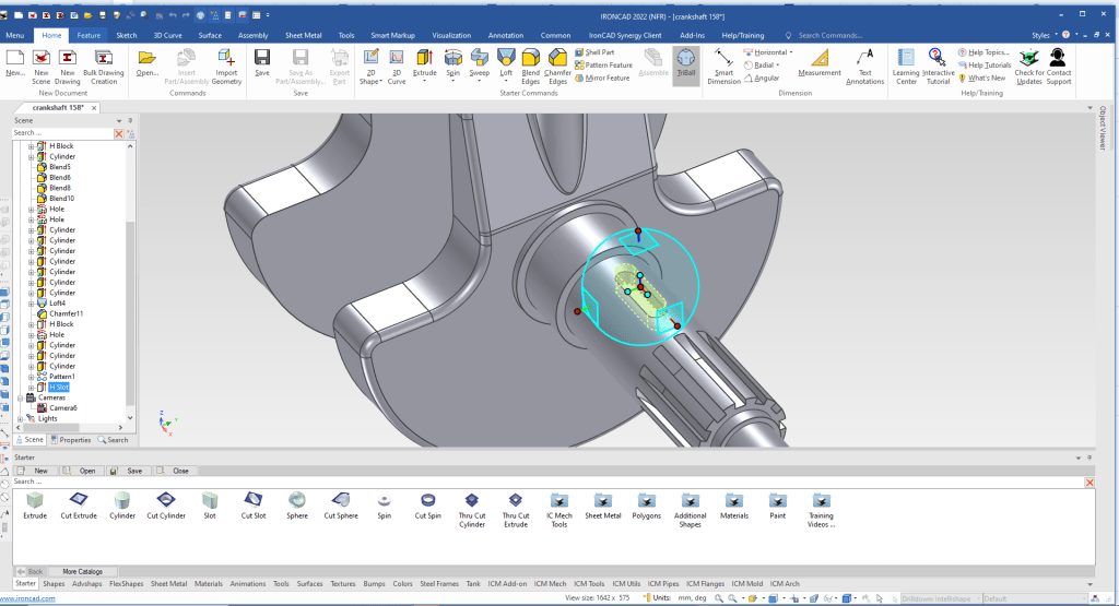
We drag and drop a “Cut Slot” on any flat surface the orients the slot. Then we size and use the Tribal to locate.
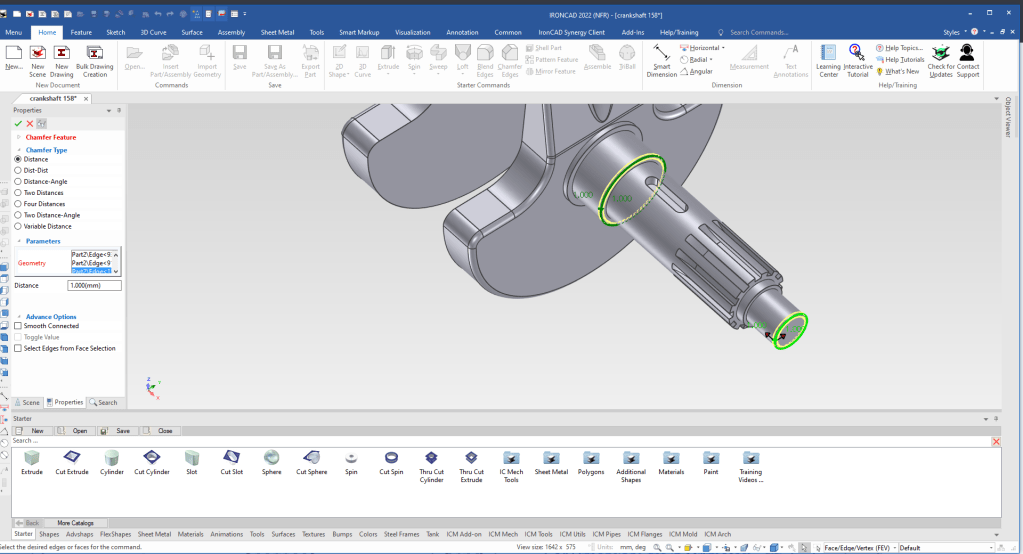
We need two more chamfers, we find the earlier chamfer in the scene browser (history) and select and chose the edit option and add the new chamfers.
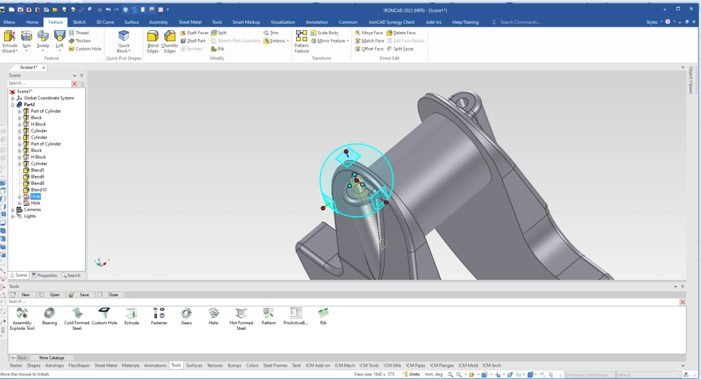
We now need to copy link the hole in the other end. Like we did with the chamfer we select the feature in the scene browser then the Triball, we move the Triball to the midpoint of the holes using the point to point option and we mirror copy link the feature.
Now for the two holes in the bearing shaft. We drag and drop a hole to a parallel face, size it and use the Triball to locate.
Then we continue to use the Tribal to copy link the other hole.
We now are done. We hide the catalog for more scene real estate.
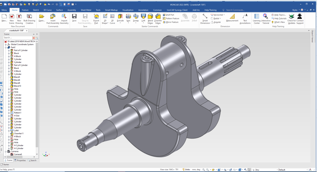
We are now done with the part. We only edited two Intellishapes.
It is very important that you look into how you or your engineers are creating the parts. Streamline Sketching and Feature Based Modeling is easy to learn and implement. It, alone, will increase productivity 10X. Now, IronCAD with its unique integrated history/direct edit functionality can increase your productivity another 5X or more with changes! Again, time is money in engineering.
More on Streamline Sketching and Feature Based Modeling.
3D Modeling Techniques Defined
To experience this increased level of productivity, please download IronCAD for a 30 day evaluation. Legacy data is no problem, IronCAD can read the native files of all of the popular programs. IronCAD is a great replacement for the subscription only Autodesk and PTC products.
For more information or to download IronCAD
Give me a call if you have any questions. I can set up a skype or gotomeeting to show this part or answer any of your questions on the operation of IronCAD. It truly is the very best conceptual 3D CAD system.
TECH-NET Engineering Services!
We sell and support IronCAD and ZW3D Products and
provide engineering services throughout the USA and Canada!
Why TECH-NET Sells IronCAD and ZW3D
If you are interested in adding professional hybrid modeling capabilities or looking for a new solution to increase your productivity, take some time to download a fully functional 30 day evaluation and play with these packages. Feel free to give me a call if you have any questions or would like an on-line presentation.
For more information or to download IronCAD or ZW3D
Joe Brouwer
206-842-0360
