What is the advantage designing with shapes?
Using shapes eliminates the need to create a sketch and extrude or revolve. If you created each feature individually it is easier to modify directly. Imagine a complex part. Give this concept a try today.
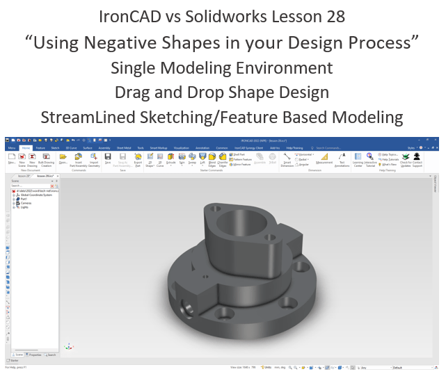
Exercise in Solidworks
IronCAD vs Solidworks
While creating 3D models from drawing is the very best way to learn 3D CAD and maybe some design techniques is does not expose the designer to the design flexibility necessary in product design. IronCAD is all top down due to the single model environment. Creating mating parts is a cruise. But modeling is just one aspect of this well designed productive 3D CAD system.
I like to show step by step lessons So you can see the commands being used.
I always create the part before I watch the Video, so as to not taint my process. Of course, there are a multitude of ways to create a model. There is no right way, just more productive ways. From what I have seen from these very complicated processes done by the Solidworks Presenters, it is not just limited by the 3D CAD system.
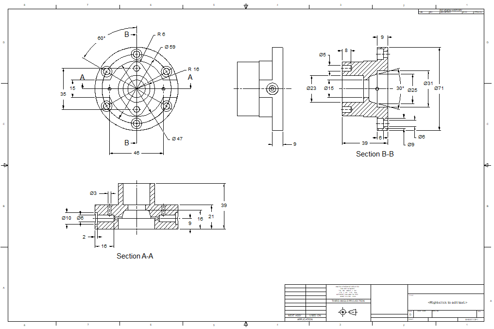
Here is the drawing if you would like to follow along.
For more information or to download IronCAD
Creating Internal Shapes with Boolean Operations
We are going to do something quite different. We are going to design a positive shape and Boolean subtract it to create an internal feature.
Many times there are internal features that would be much easier if they were positive shapes. Here is an example of that type of design.
Reverse Engineering 2015 AK-47 Project
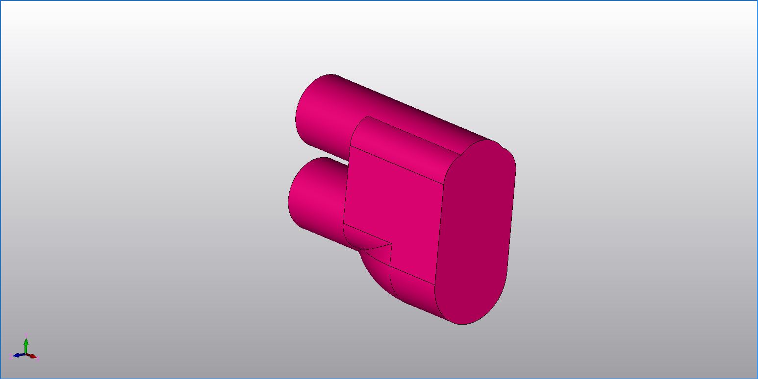
Sometimes it is easier to create a positive part and Boolean subtract it than struggling to design it inside the existing part. Here is the cavity in the back of the stock before subtracting it.
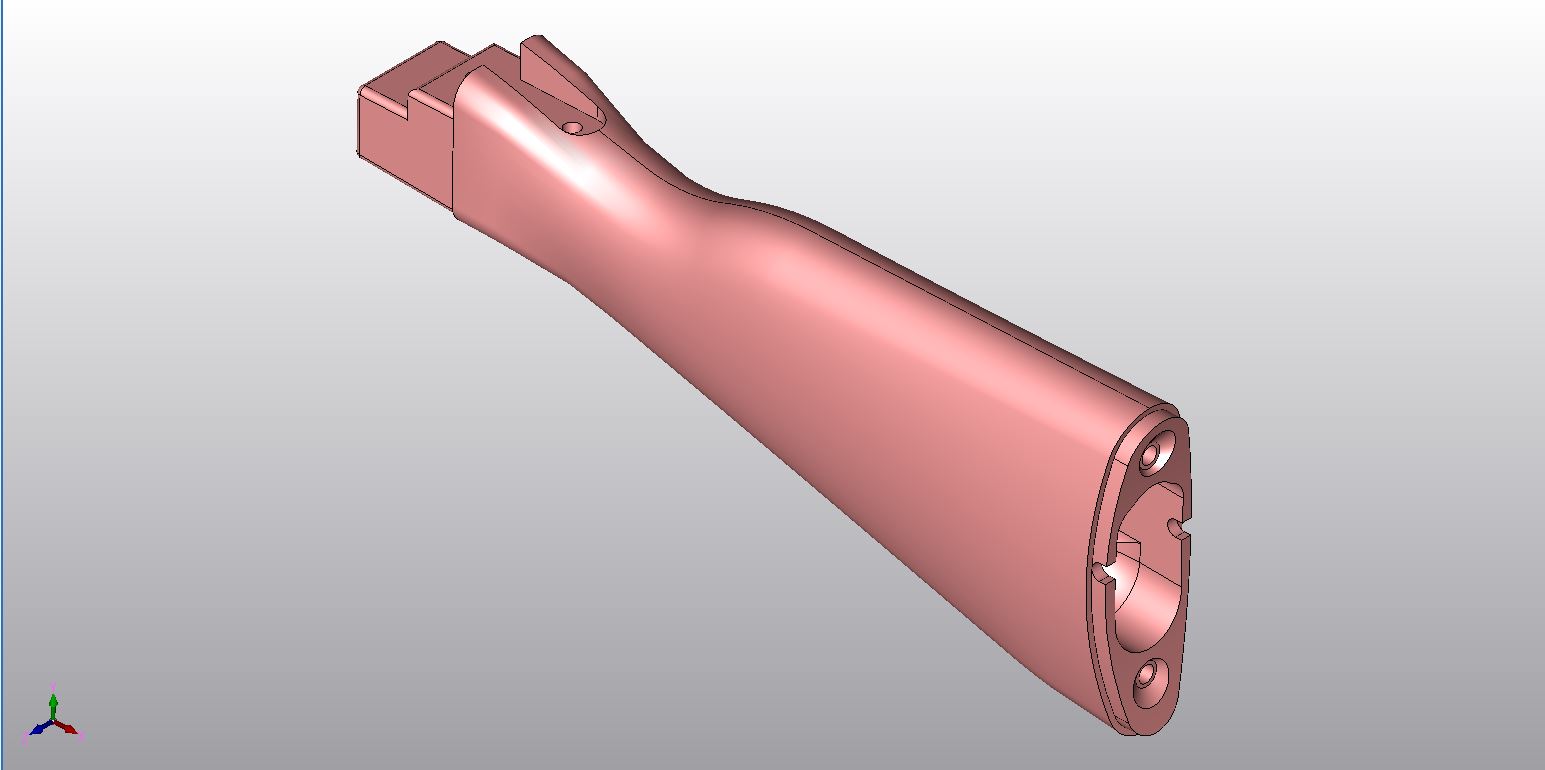
Here is the completed part. You can see that the shape is subtracted.
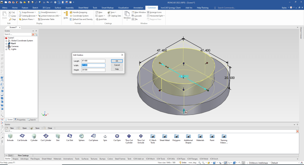
We start by dragging and dropping a cylinder into the scene and size it.
Note: Why does IronCAD call it a scene instead of a workspace? IronCAD was first released as a graphic design program called Trispectives. It still has much of the graphic design functionality. It truly is a wonderful mixture of professional 3D CAD and graphic design, which puts it in a much more flexible category as compared to the Pro/e (Creo) clones.
Also I have pinned the Catalog, you can autohide the catalog for more design space in the scene.

We not drag and drop another cylinder to the center of the exisitng cylinder. If we drag and drop with the left mouse button it automatically adds the feature to the model. If you use the right mouse button it will give you an option make a new model.
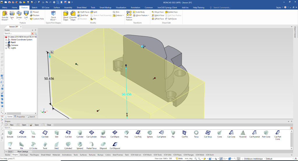
We drag and drop an extrude to the middle and using the handles we size it. We pull with the right button and is push/pulls symetrically.
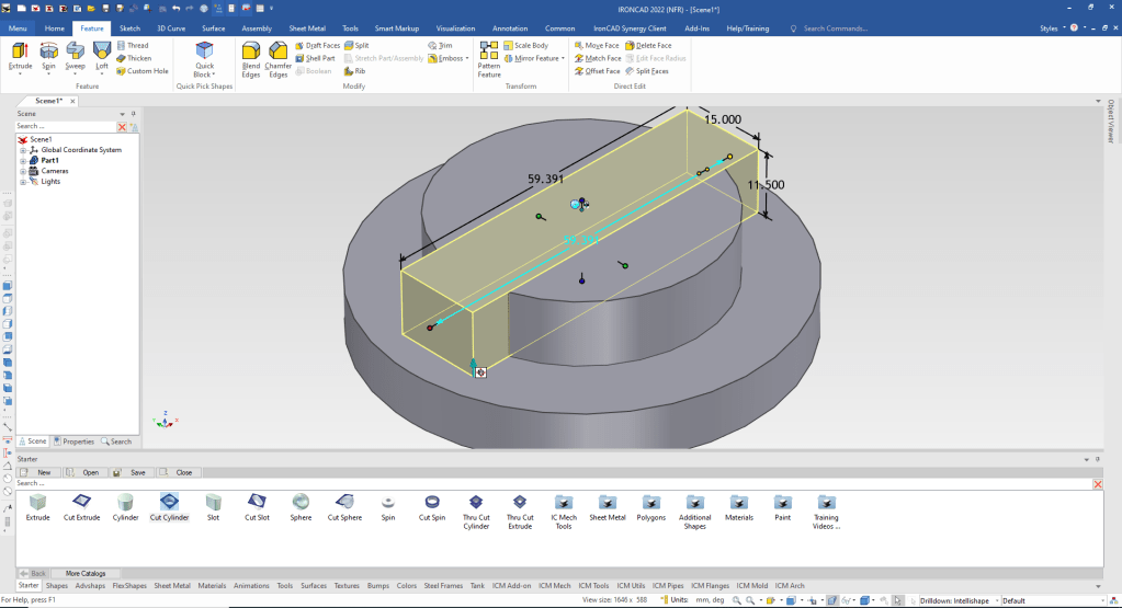
We have to have the faces of the block match the cylinder. We could use the match face command, but that would move us to direct editing. We want to stay with functional history based modeling in this exercise. We just project the cylinder edge and edit the sketch.
All of the Intellishapes are based on sketches. So click down to the Intellishape and select edit cross section.
Note: IronCAD has level of operation: First is Assembly – Yellow, Part – Blue, Intellishape or Feature – Yellow and face or surface – green.

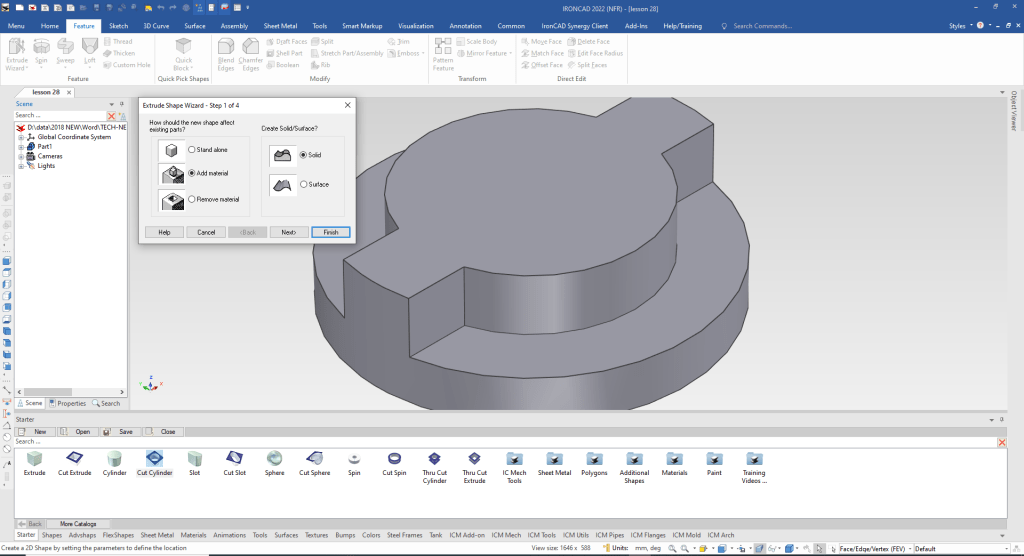
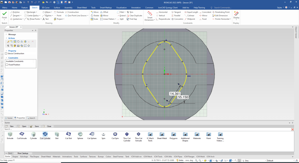
We now are now going to use a unique feature called Extrude Wizard. We select the command and locate at an set point in the center of the cylinder. We can set the extrusion height in the command.
It will bring up a sketch and we can then define the profile with robust sketching tools. Notice I use no constraints, I call this StreamLined sketching.
I used a construct line to locate the other circle then rotated copy. I am now ready to clean up the sketch. The red dots indicate problems with the sketch.
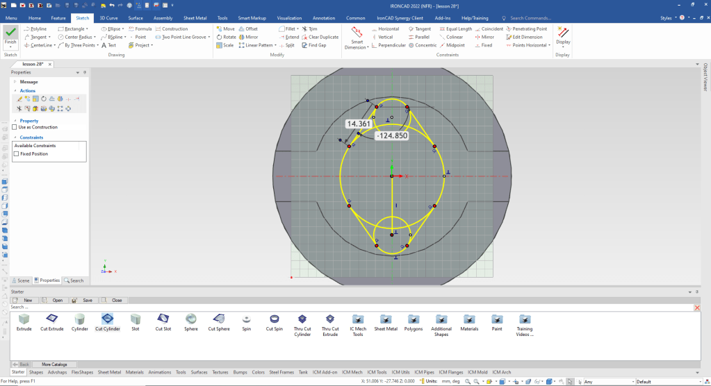
We clean up the sketch and create a good profile. You can see we are ready to save the sketch.
We are ready to create the holes for the bolt circle.
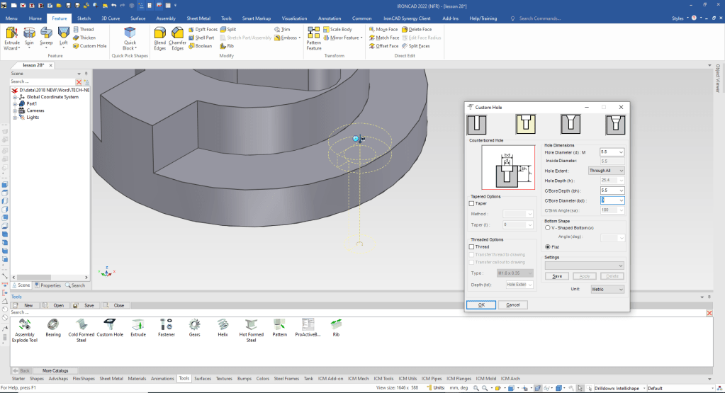
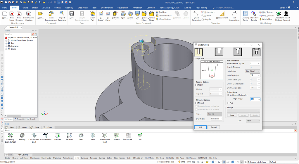
Using the Tool Catalog we drag and drop a custom hole to the face we want the hole. We can locate it later. We then define the type of hole in the custom hole dialog box.
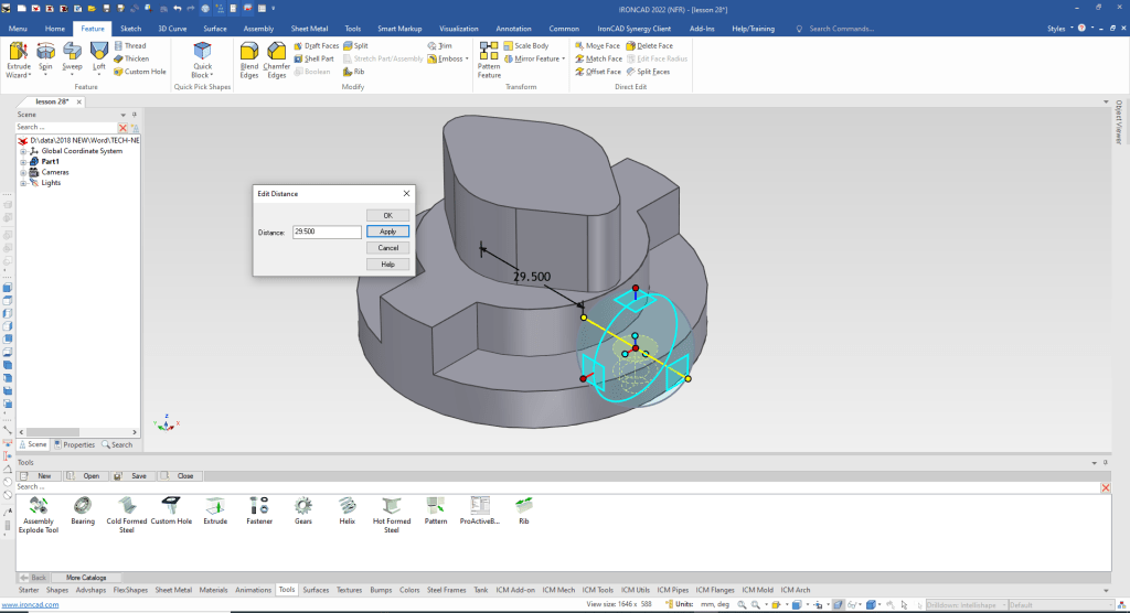
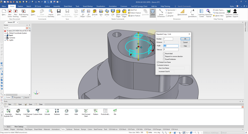
Now we locate the first hole using the TriBall.
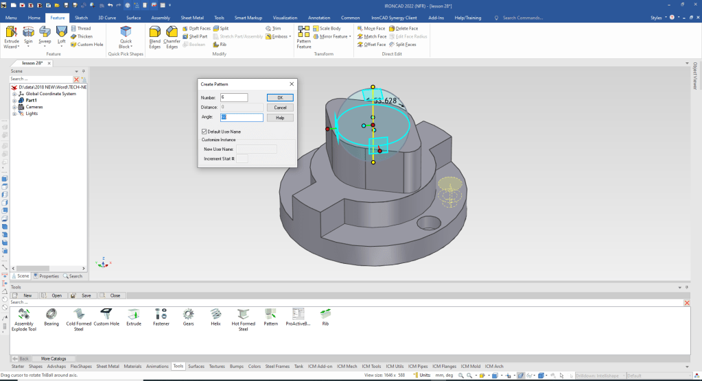
We can now pattern or copy the hole. We move the TriBall only by depressing the spacebar and select it again to activate it.
Now I will create a separate postive shape for the center cut. I am not sure I would do this with a design but I want to show you different modeling techniques.
I will drag and drop a cut extrusion for easy of model creation.
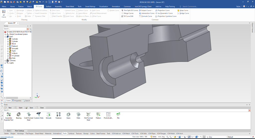
We first drag and drop the clylinders that make up this shape by using the right mouse button that will let us create a new model. We will change the color for clarity.

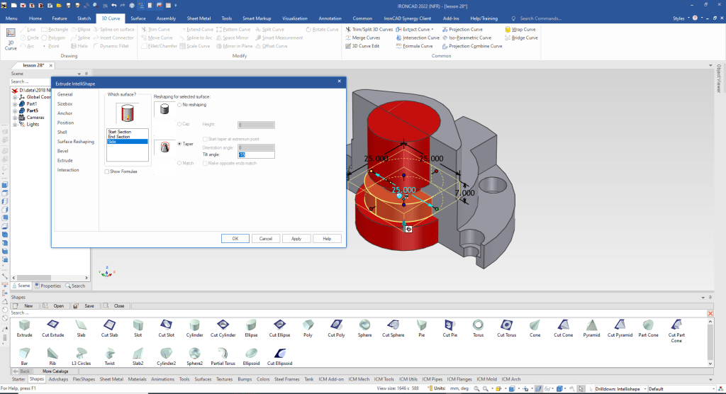
The third cylinder is tapered. We can edit the intellishape to add the taper. We select the intellishape, right click and select Surface Reshaping.
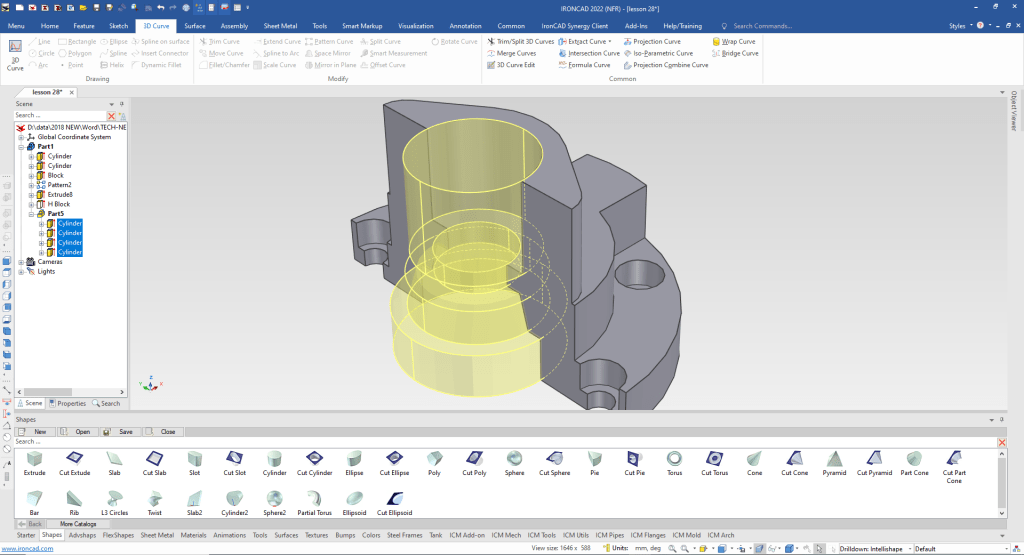
We are done with the internal shape now we need to boolean remove it from the main body. You can see the new part 5 created in the history. The sub features can be edited at any time.
We edit the cut extrusion to show the other half of the model. This is for ease of modeling.
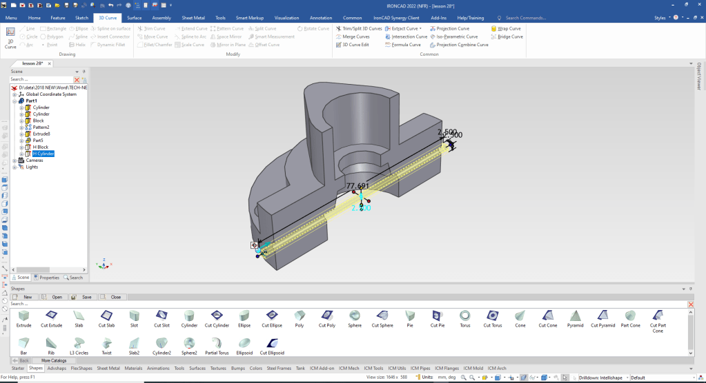
We will first create the through hole.ds We will drag and drop it on a flat face and locate it with the TriBall.
We will use the Tool catalog and custom hole. Again we will drag and drop it on a flat face and define it with the custom hole dialog box. Then we will use the Triball to locate it.
Now we have to rotate copy the new feature.
Now the two top holes. We suppress the cut extrude, we probably don’t need to keep it here, but as we design it is always a useful tool to have available.
Again we go to the tool catalog and select the custom hole tool and set the size.
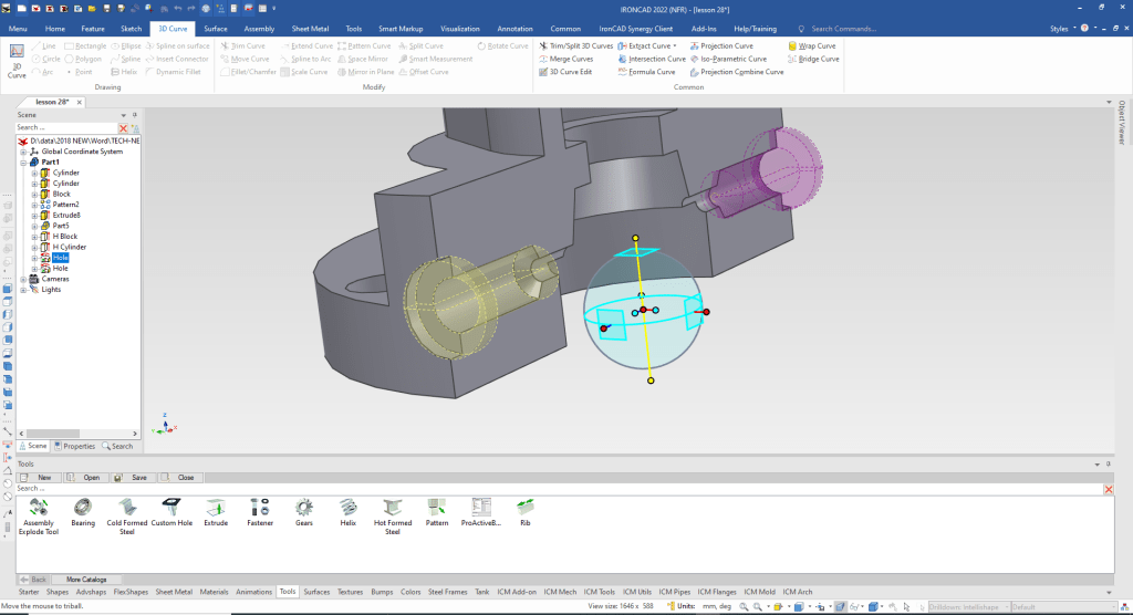
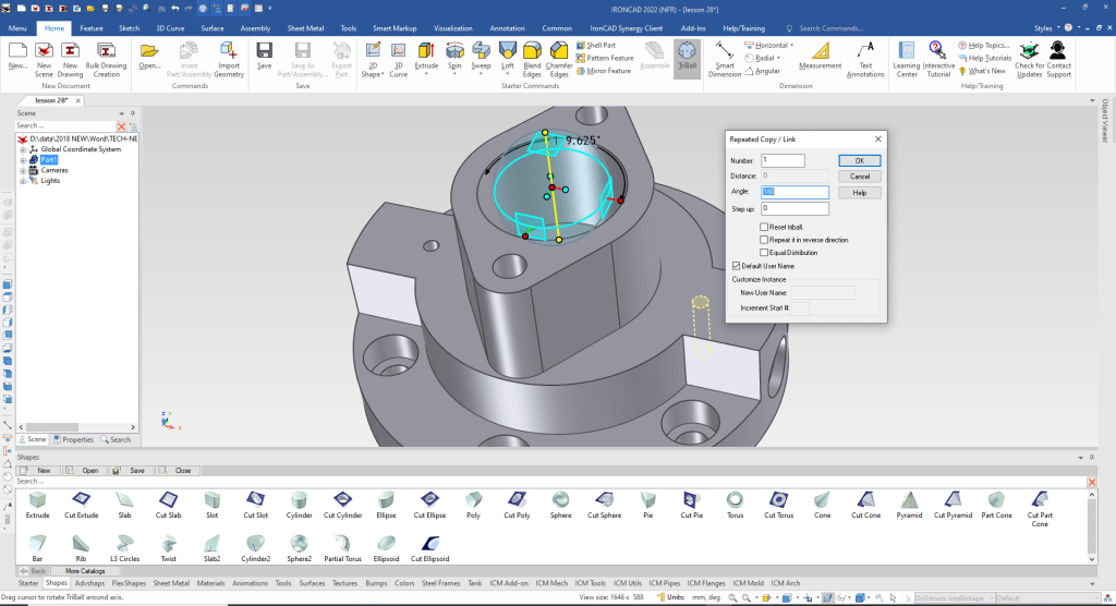
We rotate copy link the hole. Linking means you can edit one or any of the link copies and they all change.
Now for the two small holes. We drag and drop a cylinder locate and size it and using the TriBall we rotate copy link the other hole.
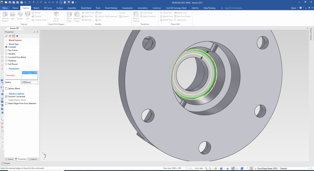
One blend.
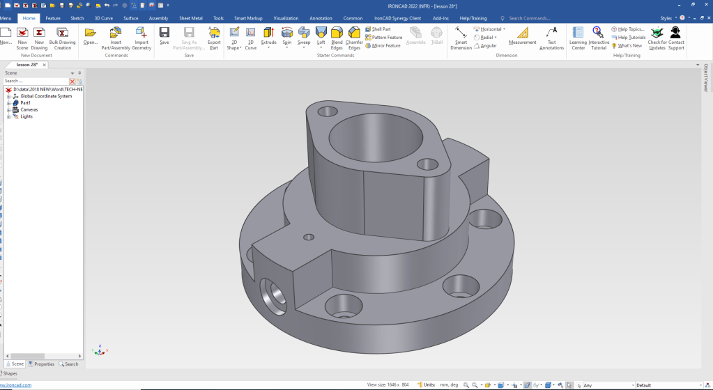
We are done with part one sketch and one edited intellishape. We hide the catalog for more scene real estate.
It is very important that you look into how you or your engineers are creating the parts. Streamline Sketching and Feature Based Modeling is easy to learn and implement. It, alone, will increase productivity 10X. Now, IronCAD with its unique integrated history/direct edit functionality can increase your productivity another 5X or more with changes! Again, time is money in engineering.
More on Streamline Sketching and Feature Based Modeling.
3D Modeling Techniques Defined
3D Modeling Techniques Defined 2
To experience this increased level of productivity, please download IronCAD for a 30 day evaluation. Legacy data is no problem, IronCAD can read the native files of all of the popular programs. IronCAD is a great replacement for the subscription only Autodesk and PTC products.
For more information or to download IronCAD
Give me a call if you have any questions. I can set up a skype or gotomeeting to show this part or answer any of your questions on the operation of IronCAD. It truly is the very best conceptual 3D CAD system.
TECH-NET Engineering Services!
We sell and support IronCAD and ZW3D Products and
provide engineering services throughout the USA and Canada!
Why TECH-NET Sells IronCAD and ZW3D
If you are interested in adding professional hybrid modeling capabilities or looking for a new solution to increase your productivity, take some time to download a fully functional 30 day evaluation and play with these packages. Feel free to give me a call if you have any questions or would like an on-line presentation.
For more information or to download IronCAD or ZW3D
Joe Brouwer
206-842-0360
