ZW3D Training – Lesson Two
Importing Parts and Assemblies for
Modification, Tooling and New Design
Download a 30 day fully functional Integrated Evaluation Copy of CAD/CAM ZW3D and follow along.
For more information or to download ZW3D
Because many of you may be coming from other systems and need to work with existing systems or you may be a supplier or machines show and work with clients with different systems. Lesson 2 will focus on importing parts and assemblies for the different import formats.
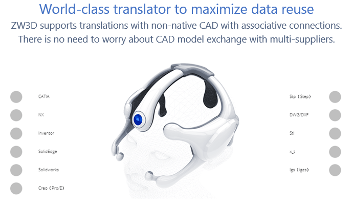
ZW3D can import the standard formats STEP, IGES, Parasolid, DWG/DXF, ACIS and Native formats from NX (PMI), Solid Edge, Solidworks (PMI), Creo (PMI), Catia 4/5 (PMI), Inventor and Rhino.
ZW3D also has a drawing import option for Catia 5 and Solidworks.
All of these translators are included in all of ZW3D 3D CAD/CAM products.
I will not go through every system just show you how to work with imported parts and assemblies.
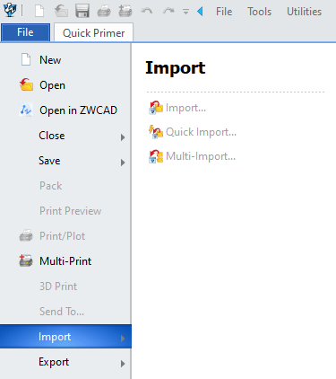
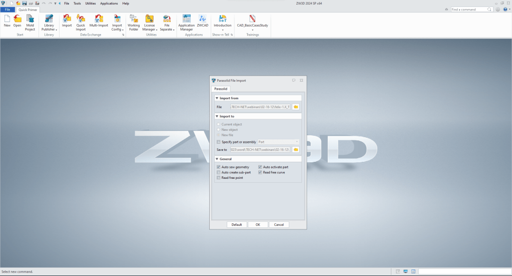
We can import a file a couple of ways from the opening page or from File>Import. You can see three options. As you use the product you will decide which option to use for now we will use first import command.
We won’t focus on importing a single part. Most of us have done that many times. But what we are going to focus on is a complex assembly with many subassemblies.
Here is a very large assembly created in Solid Edge and exported as a parasolid (.x_t) file. This is an example of how we can use a generic neutral CAD import, and bring the complete assembly into a single file which is much more productive. Of course, with conventional 3D CAD system importing these would fill a folder with all the referenced parts and sub-assemblies.
We will import felix-1.x_t. This is a 50,220 KB file.
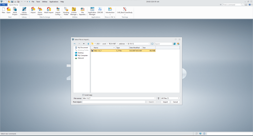
We have a few option, we will accept the default.
It takes less than minute to load.
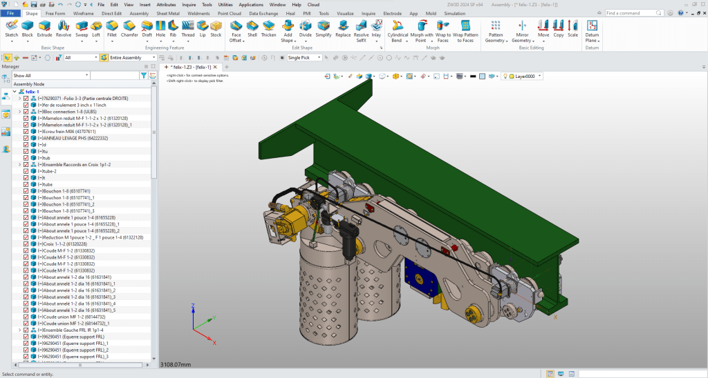
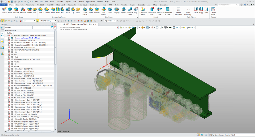
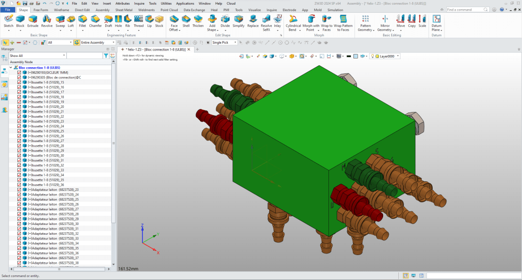
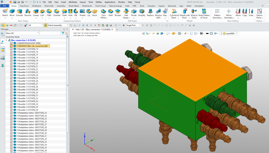
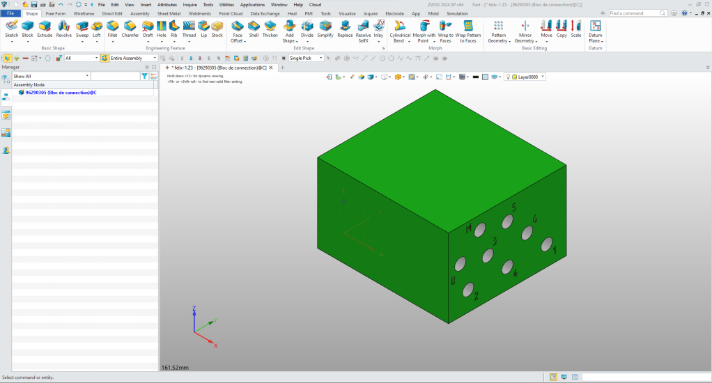
You look a the object manager on the left can see the parts and sub-assemblies with their full names. We have selected the “Bloc connection 1-8 (UL8S)” sub-assembly you can now edit the part or sub-assembly in context or top down.
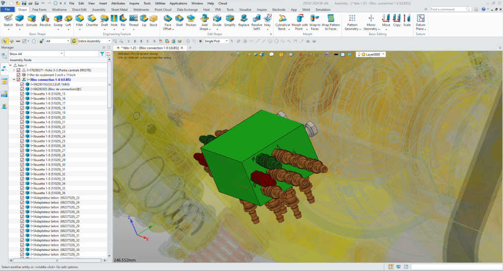
We can also open the sub-assembly. We can instantly see that this assembly was inserted into the assembly since it has a different origin than the top assembly. We will get into design in aircraft position where the parts are designed top down in a later lesson.
Let’s continue down open a part.
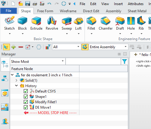
We can select the part in the work space, from the object manager (shown above on the left) or we can go to the ZW3D Manager. You can see that the parts/sub-assemblies are numeric/alphabetic order. You can see the “Bloc connection 1-8 (UL8S)” has been selected.
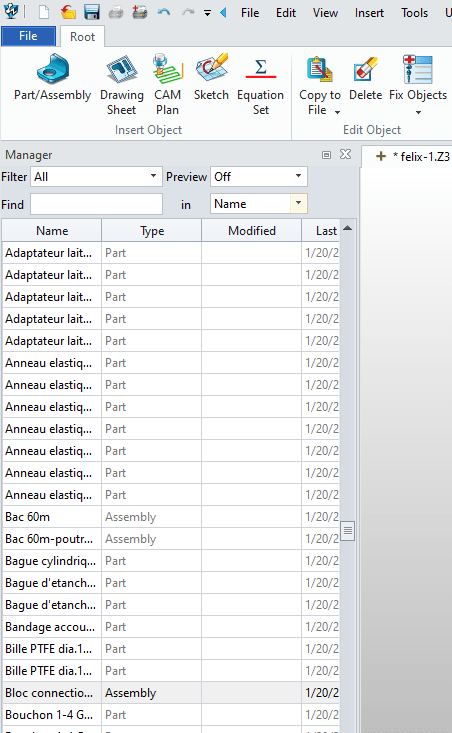
When we click we go to the selected sub-assembly.
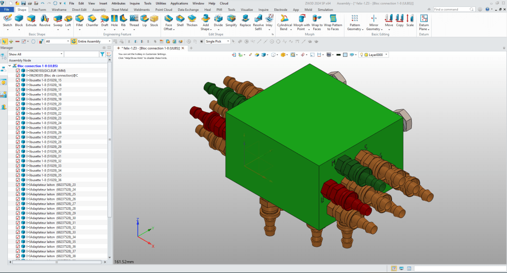
Now will open a part by selecting it in the work space and open the part. This
As we right click (pushing the right mouse) a dialog box comes up with many options. We will go to the bottom and select “open” (The open folder icon). If we select edit we can modify the part using the adjacent parts.
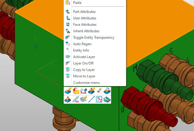
We now have the Bloc to edit or modify.
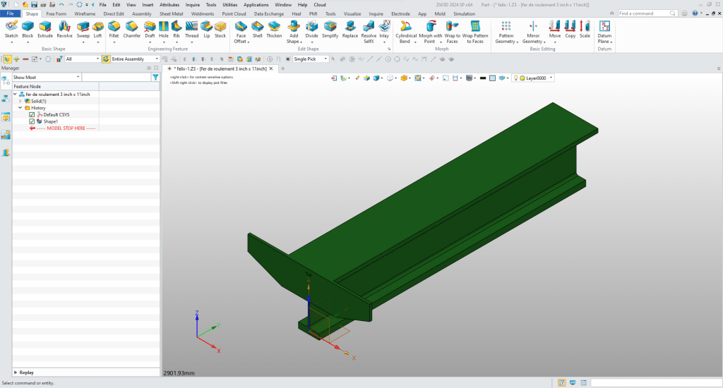
Direct Edit Modification
Let’s do a bit do direct editing or modifying by opening the Felix-1 assembly in the ZW3D manager. We will open the “fer de roulement 3 inch x 11 inch” part. Again you can see it comes in with a different origin and orientation.
We can change the fillets from 27.4mm to 50mm.
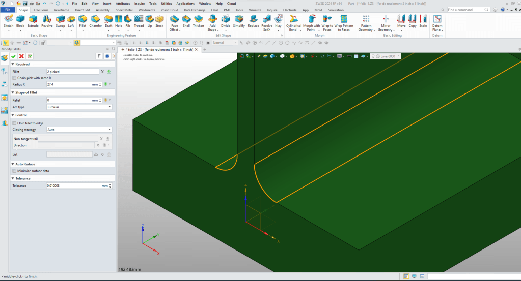
You can see that they have changed.
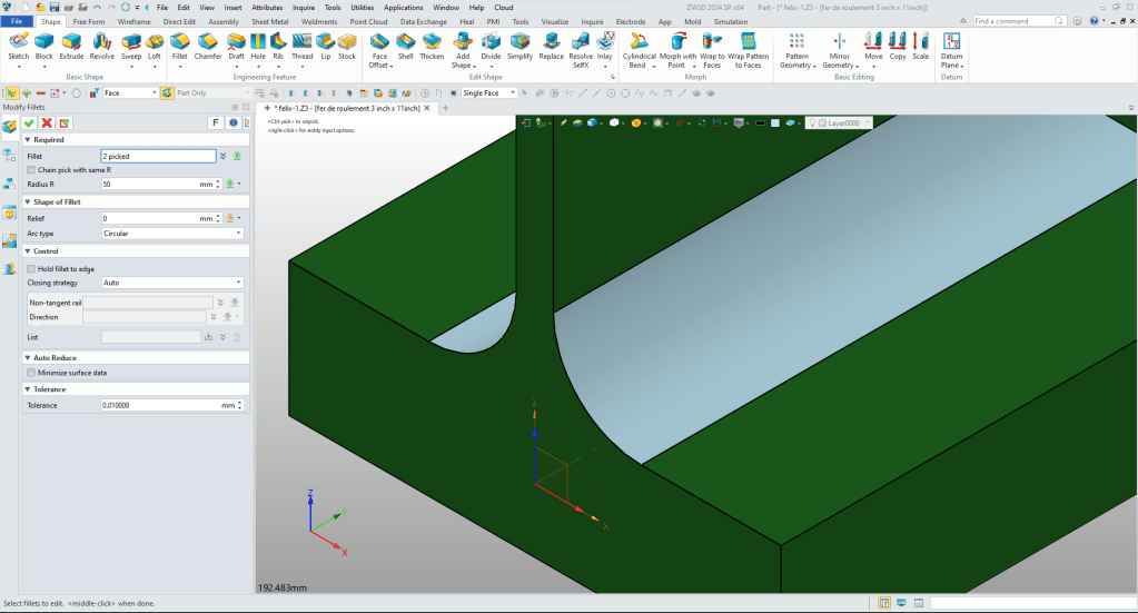
Now do another change. We will thicken this face. We select the two faces using the CTRL key. We click the right mouse button a dialog box comes up with options. We select the “DE Move” icon on the upper left of the box and the control panel comes up and we select the 3rd box from left “Move entities along a direction”. We select the directing and distance. You can a preview to the move completing the step.
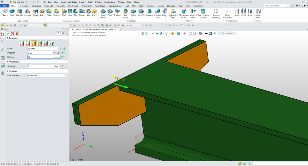
You can see that we have increased the thickness.
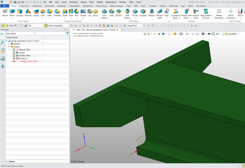
Now these are very easy direct edit functions. You can now see that both the fillet and face modifications are now features in your model. ZW3D is designed to have all the design options at your finger tips.
We have shown how you can work with a large assembly in using the Multi-Object environment to design or to import to simplify your work.
We will have a Direct Edit Lesson soon.
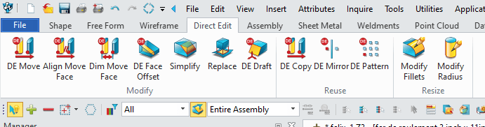
You can see from the ribbon tools the amount of direct edit functionality you have. When you work with an imported model you will use these tool.
Tooling and New Design
But what if you want to use the part to create some tooling or to do some new design? Working top down or in context is the best way to operate on assemblies from other systems.
I think that will get you going. If you have questions. I am available after 5 AM to around to noon PDT for questions. We can share screens on Skype.
Joe Brouwer 206-842-0360
We sell and support IronCAD and ZW3D Products and
provide engineering services throughout the USA and Canada!
If you are interested in adding professional hybrid modeling capabilities or looking for a new solution to increase your productivity, take some time to download a fully functional 30 day evaluation and play with these packages. Feel free to give me a call if you have any questions or would like an on-line presentation.
For more information or to download IronCAD
Joe Brouwer
206-842-0360
sales@tecnetinc.com
