
We are decades past the last of the manual drawings. Most the Industrial Mechanical Industry only uses the electronic drawing programs as a small part of their engineering documentation. Most use a 3D CAD package.
How did we develop our designs Pre – 3D CAD
As I ponder on my first 17 years as a draftsman, pre-3D CAD, we developed our designs by doing the “Design Layout”.
My First 17 Years or “How did we do it without 3D CAD!”
The Design Layout
The layout was a form of drawing, it had no real standards, it was used to develop the design. It was done on unformatted vellum. It was mostly a description of the top or sub assembly, used to develop sheet metal parts or tubing, to do kinematic studies of mechanisms and more. Most every drawing was developed on a layout.
It was done by both engineers and draftsmen. Most of the aerospace industry used draftsman under the guidance of a Mechanical Engineer, fondly called the “ME”.
I only worked at one place where they had only engineers doing the “layouts”. It was Pratt and Whitney. They had an engineer only design department. They would do the layouts and release them to the Drafting Group.
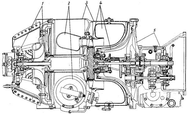
They were documented and recorded and were official documents. They had really no standards for format. Most were parts, but all gas turbine companies had an ongoing cross section that was maintained by either a board engineer or a senior draftsman.
They looked similar to the image below. But they had many critical dimensions. The other features would be developed on the “drawing”. Aircraft and other large programs that had different departments for the different functions of the projects.
I worked at two gas turbine engine companies’ pre-3D CAD, Pratt & Whitney and Williams International. They had different design philosophies. Engineering was made up of engineers, draftsman and checkers.
Pratt had a separate design department and drafting group.
Williams had the drafting group doing all the layouts under the guidance of the “ME”. We would get a print of the layout cross section and develop the parts. Most aerospace was like this.
In both philosophies, drafting was responsible for all form, fit and function, tolerances and the correctness and quality of the drawings. Both companies had a staff of checkers. A checker is an experienced senior draftsman that checks the design, form, fit and function and drawing correctness. They were the final authority for release of the drawing.
Here is an example how it worked at Pratt. I received a layout from engineering, it was heat shield for the after-burner ring. The shield was in two pieces designed radially. I said, wow, his is going to be a horror show to create the tool. I recommended they design it on the side. My drafting lead and supervisor let me do a layout and they presented it to engineering. The engineer came down and took the layout to be redesigned.
Aircraft and other large projects that had different departments for the different components of the projects. The layouts were handled much differently. The layouts were used only to develop the design. Much of it was defining installation of primary or secondary structure or equipment. Most were not official documents. Once the part and assembly drawings were done the were the design authority.
Here is an example of how it worked. I did a layout to install an extra fuel tank in the cargo compartment of the 737 while at Boeing. Yes, I was a design draftsman. It had to fit through the cargo door and be installed. Not much room. I had to develop the cross section and develop the envelop. I worked with a “ME” to design the support brackets. It was funny I was reprimanded for drawing the HI-LOK fasteners on the edges of the tank. It was a no-no at Boeing to draw fasteners. But I explained to the engineer that they were part of the envelop. I only showed a few at the beginning and end with a phantom line defining the space. They were really not drawn, we had a template for every fastener. Now that I think of it, he should have seen that.
Another example: I was responsible for installing the mechanism for the escape slides on the 747 doors and it was to be attached to the door mechanism. I had to do a kinematic study of the lower door flap. You would draw the components in the different positions. I found that the bottom door flap mechanism ran into the structure. I showed my supervisor and he agreed. I took the layout to the door group and they thanked me!
The design layout was where everything was developed. They were mostly done by design draftsmen. The design engineers that did layouts were called “board engineers”. The last thing most engineers wanted to be was a “board engineer”. Rarely, did a board engineer get promoted into management which was the goal of most engineers. They basically became glorified draftsmen.
3D CAD
How did engineering include the layout into the implementation of 3D CAD?
3D Wireframe
I was introduced to 3D Computervision CADDS 4 while on my 2nd contract to Williams. Parts were developed in 3D wireframe then you would detail instances or views generated from the 3D model that were created in the documentation module.
The 1980’s – 3D CAD – The Beginning
But the layouts were still being created manually on the drafting board. You could not effectively do assembly design on wireframe CADDS 4 at the time. It was monochrome, green graphics on a black background. Even when they finally got color it was still very difficult to present.
In 1986 I was introduced to PC based 3D CADKEY while on contract at Boeing which was equal to CADDS 4 and Catia 2 since all were 3D wire frame.
You could do assembly design using different levels. But it was very difficult to differentiate the parts by just defining different colors.
Here is what it looked like. Are you looking up or down? It was tough working with 3D wireframe. It drove the poor “ME” crazy.
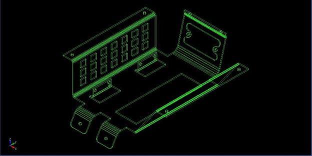
I convinced the Boeing supervisor to allow me to do the design for the cabinet for the first observers station on the 747-400 on CADKEY. I worked with a “ME” to do the design. We did the design in “Aircraft Position” which we knew the WL (waterline), BL (butt line) and SLA (station), that was the X-STA, Y-WL, Z-BL looking at the right view of the airplane.

We would get outer loft lines for the two stations we would be working from Catia. We would do the offsets of these lines to represent the frames to develop the clearance for the cabinet. We would go to the undimensioned drawings to develop the frames in 3D. It is interesting that IGES was fully functional for transferring graphics between CADKEY, CV and Catia. When it was 3D wireframe there was no history or relationship between the entities.
We would develop the flat pattern from the 3D and create them on another level.
We could then open up a “Layout Mode” (What CADKEY called their drawing space) and create the drawing for the finished part in the documentation module by placing views or instances and detailing them in a defined format. But they weren’t really drawings were they? What were they? The Boeing draftsman coined them the “Flat File”.
It those days much was developed on the board with layouts with a mix of 3D CAD to develop the drawings. Remember 3D CAD was only for creating drawings at the time.
We could create a .dxf from the flat pattern and send it to the sheet metal CNC machines. This was a few years before surfacing allowed 3 axis CNC.
Surfacing -1988
Surfacing became widely available and useable in 1988. CADKEY had a fully functional mid-ranged FastSurf addon. Both CADDS4, Catia and other systems had surfacing available.
The 3D world changed. Now, surfacing did not aid design much more than developing intersections, but it could now be used to create net surfaced parts for 3 axis machining and 3D printing. Many 3 axis CAM systems appeared on the market, they were all PC based and were being used by the suppliers. I started selling CADKEY at time supplying all the Boeing suppliers a CAD system that was compatible with Boeing’s Catia mainframe system. Now Surfacing did not add to the layout functionality except to provide cross sectional graphics. CADKEY was unique since it could create drawing by locking the top view. We could do our layouts on one level, then take the graphics to generate the 3D models for detailing.
3D wireframe could be used directly for 2.5 axis work, but when net surfaced could drive the 3 axis CNC. Net surfacing was not easy with the intermediate surfacing tools. Surfacing was widely used until 1995. Again IGES was a functional translation tool for wireframe and surfacing.
Solids
Functional solids were being deliver as IGES surface files from PTC’s Pro/e system in 1988. This was revolutionary, it was delivered on a Unix standalone system. By 1994
Solids were now in Catia 4, it was introduced on the PC CAD systems in 1995. With two solid modeling kernels available, products like CADKEY’s FastSolids, Trispectives, Solidworks and a few other CAD packages started delivering functional solid modeling.
The 1990’s – 3D CAD/CAM Moves to the PC!!
Now with all that explained let’s get back how this relates to the design layout.
Solid modeling now offered a new level of design. Unlike wireframe with solids we could get real time hidden line removal. When we now created the instances or views in the documentation module, all of the hidden lines were removed, with wire frame you had to trim or blank the unwanted entities. It was a tedious chore we endured until the release of solids.
We would model the assembly “layout” and it could be used to access the parts to create the “flat file”. But we could now use the solid models for CNC, CAE, .stl for 3D prints, graphics for Tech Pubs, manuals, marketing, it actually replaced the technical illustrator. We had IGES (yes, it would translate solids), STEP, parasold and ACIS to translate the models to and from other systems.
Now that the model could be used for other purposes the document went from the “flat file” to the AID (Associated Information Document) that now traveled with the 3D model.
Now the 3D assembly would be the official design authority.
In CADKEY we designed in a single model environment so we could use common features to create the mating faces. Trispective turned into IronCAD that also had the single model environment which would lead to “top” down design. I was contacted by Solidworks to sell their product in 1998. I took a look at it and couldn’t believe how complicated it was. CADKEY was a direct edit program but could do the part, assembly and drawing in one file. IronCAD is the only integrated history/direct CAD program. It had a separate document module, so the part and assembly were in one file and all the drawings were in another.
So Solidworks, and now, I considered Pro/e being a huge step backward.
But that is a bit of an aside to the topic at hand the “design layout”
In the beginning 3D CAD was only being done by draftsmen. They would still do the development under the guidance of the “ME”. But when Catia 5 was released on the PC, things changed, and the large aerospace companies decided to move the engineers to the CAD system.
The Death of the Draftsman or “Where has all the talent gone?”
I remember at Solar Turbines they let all the direct CAD draftsmen go in 1985 and moved the engineers to the CADDS 4 system. The engineer either got on the CAD system or were fired. I was the last draftsman there and I was to train the engineers. I had a problem with the new CAD manager and moved on. But I had heard from some of my old contractor friends that moving the engineers to CAD was not practical and they brought on a new crew of CADDS 4 draftsman contractors to do the 3D CAD work.
Solar Turbine like most of the CV users moved to Pro/e.
But Boeing and much of Aerospace got rid of the complete drafting group and replaced them with engineer.
Can Engineering Survive without the Drafting Group?
Back to the layout!
No matter who was designing the assemblies the parts and sub-assemblies had to be delivered as authorizing drawings. They tried to use the draftsmen who now were Engineering Techs to do the job. They would give them a single part to detail and the drawings were a disaster, since they did not have the mating parts no effective tolerancing could be done. They blamed the draftsman, and rightly so, it was the draftsman’s lack of experience to not demand the compete assembly before doing the detailing. It became quite a mess!
What they should have done is treat the 3D assembly like a layout and give it to a drafting group that would have scrutinized the design and release the documentation as they did before. The engineer could have focused on what was important and what was not.
But that never happened and now the engineer is not only responsible for the design, but the form, fit and function, detailing and checking.
Engineer’s Job Description
The Search for the Purple Squirrel
It is a poor use of an engineer’s time. I see engineers now touting their 3D CAD skills. Many, today, are not much more than glorified 3D CAD draftsmen.
I sort of feel insulted when I make that statement. But the draftsman was responsible for I would say 80% of the quality of the engineering and documentation of the past.
TECH-NET Engineering Services!
We sell and support IronCAD and ZW3D Products and
provide engineering services throughout the USA and Canada!
Why TECH-NET Sells IronCAD and ZW3D
If you are interested in adding professional hybrid modeling capabilities or looking for a new solution to increase your productivity, take some time to download a fully functional 30 day evaluation and play with these packages. Feel free to give me a call if you have any questions or would like an on-line presentation.
For more information or to download IronCAD or ZW3D
Joe Brouwer
206-842-0360
