What is the advantage designing with shapes?
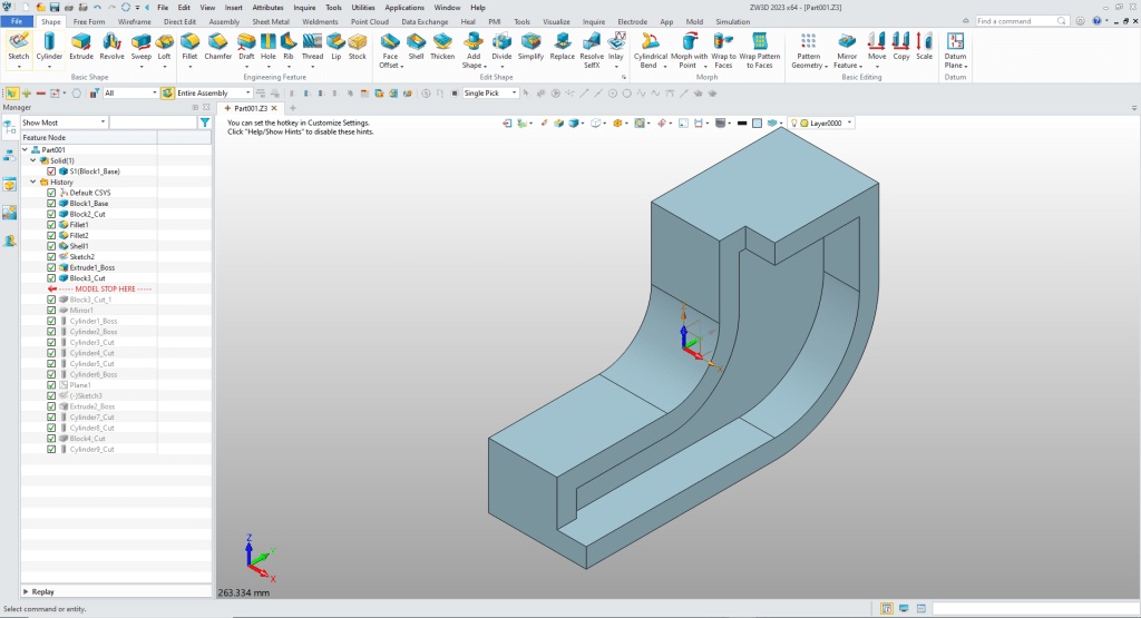
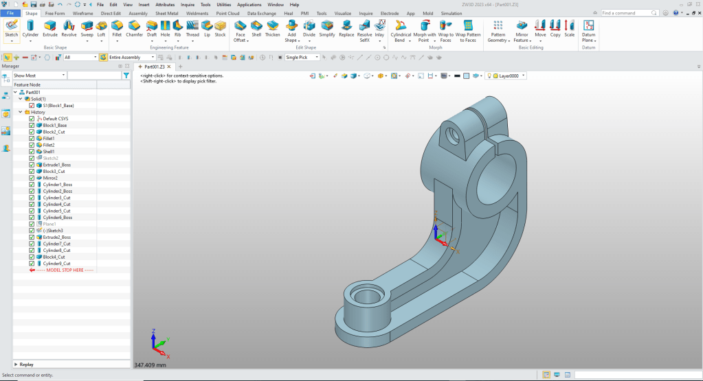
Using shapes eliminates the need to create a sketch and extrude. The above part has 14 shapes and 2 sketches. This is a simple part and we have eliminated 14 constrained sketches and 14 extrusions. Imagine a complex part. Give this concept a try today.
The modeling technique is hugely responsible for the level of productivity. Those of you that are only trained in the sketch, sketch, constrain, constrain world are truly limited by not using the freedom of Streamlined Sketching and Feature Based Design, that is available in even the most Pro/e-ish of CAD systems. If your designers are designing in these very unproductive and time consuming processes it might be time to review your standard design processes. Don’t have any do you?
ZW3D is a sketch based system so it is easy for the major CAD system users to get up to speed fast. But it also has Primitive Shapes available that can eliminate the need to sketch and extrude in many cases.
I saw the following video challenge on linkedin and thought I would give it a try. I actually did it before I watched the video, so I did it a bit differently. This will give you an idea how different and flexible ZW3D is compared to the conventional Solidworks
SolidWorks tutorial for beginners exercise 131
While creating 3D models from drawing is the very best way to learn 3D CAD and maybe some design techniques is does not expose the designer to the design flexibility necessary in product design. ZW3D can be set up one part per file or multi-object which offers incredibly flexible top down design. Creating mating parts is a cruise. But modeling is just one aspect of a well designed productive 3D CAD system.
ZW3D is one the few 3D CAD systems that has integrated drawings, so you can do complete projects or sub-assemblies in one file.
I would do a video, but I really am not good at it. So I will show you step by step.
I always create the part before I watch the Video, so as to not taint my process. Of course, there are a multitude of ways to create a model. There is no right way, just more productive ways. From what I have seen from these very complicated processes done by the Solidworks Presenters, it is not just limited by the 3D CAD system.
Here is the drawing if you would like to follow along.
Download ZW3D and follow along
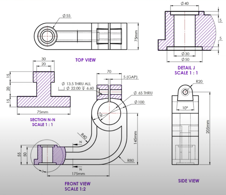
We will create this model using primitive shapes only. Using shapes eliminates the need for the sketch and extrusion.
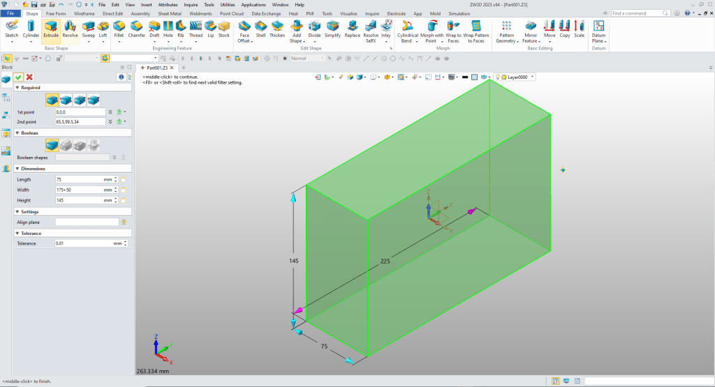
I insert a block and size it.
I insert another block on top of the existing block locate and size it an set it to remove.

We create the two fillets.

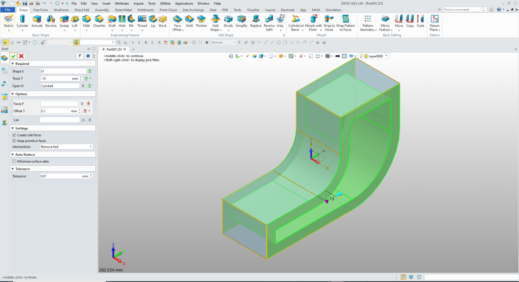
We shell the part.
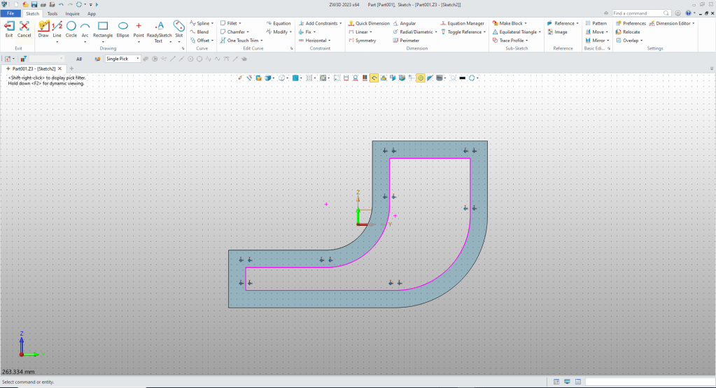
We need to create the middle web so we create a sketch on the middle plane and project the reference edges.
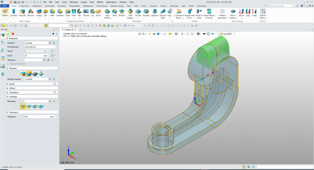
We extrude with a symmetric option and set the extrusion to 20mm and set to add.

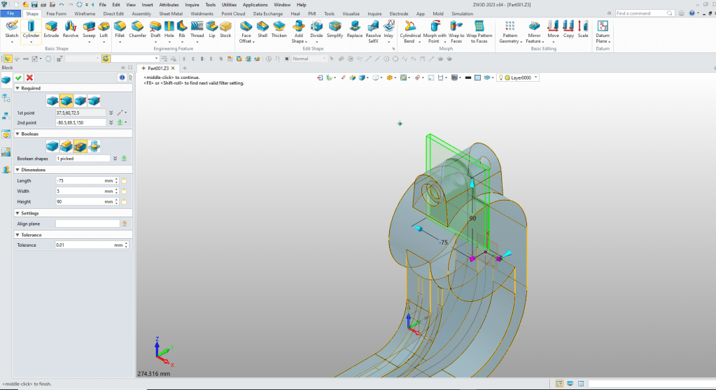
The upper rib is thinner so we insert a block locate and size it and set it to remove.
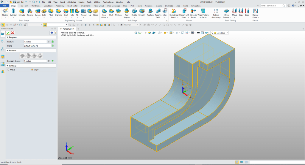
We mirror copy the feature.
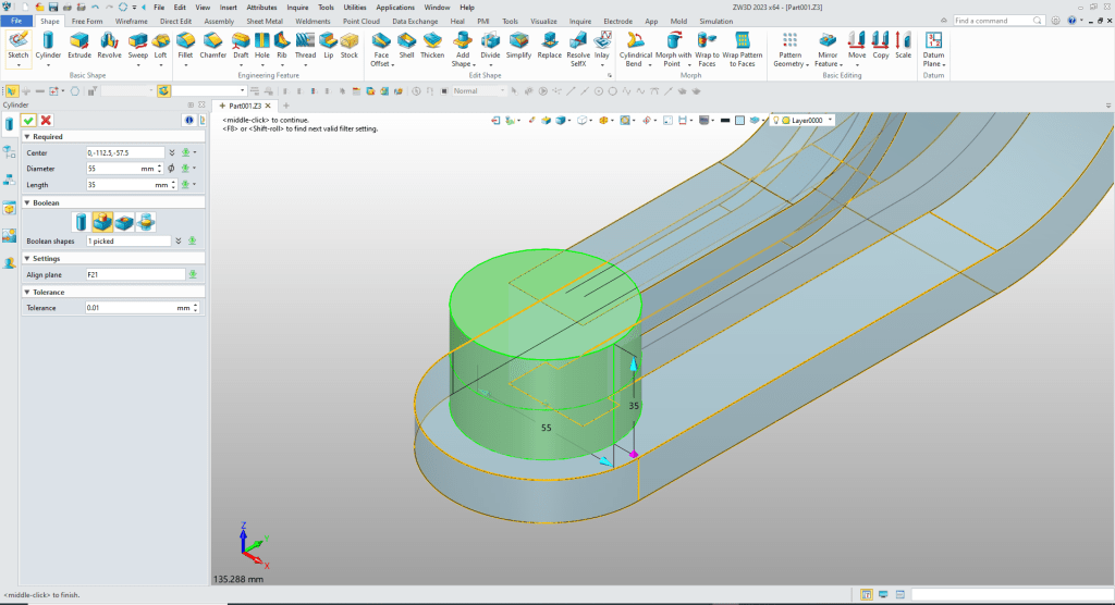
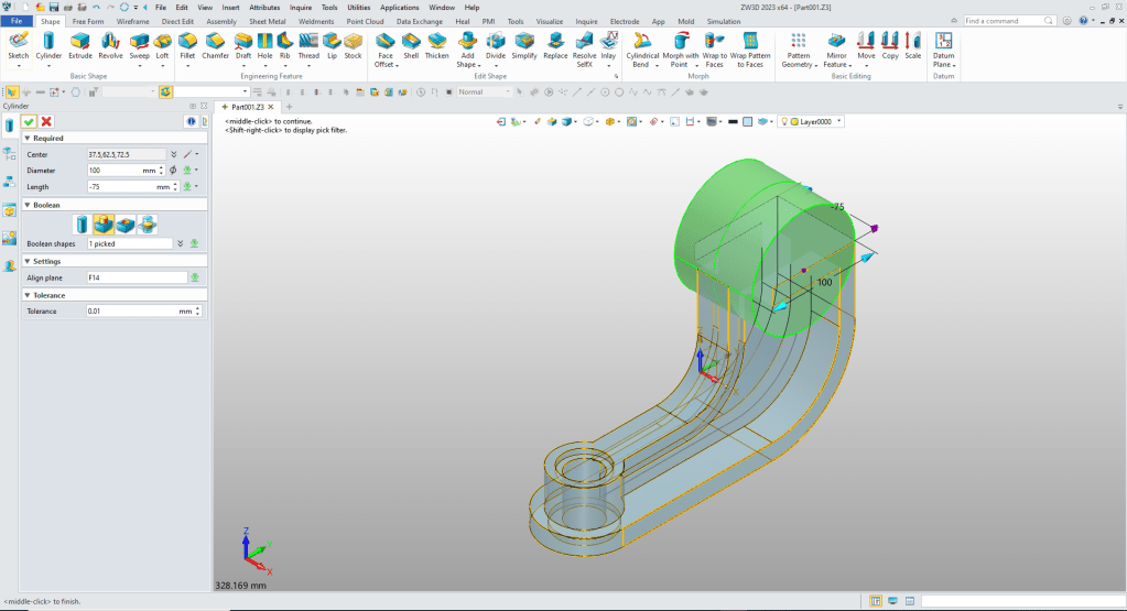
We insert a cylinder locate it at mid-point of the front edge align it to the bottom and size it and set it to add.

We insert a cylinder at the front edge size it and set to add.
We insert the cylinders at the center of the boss and create the two counterbore and thru hole.
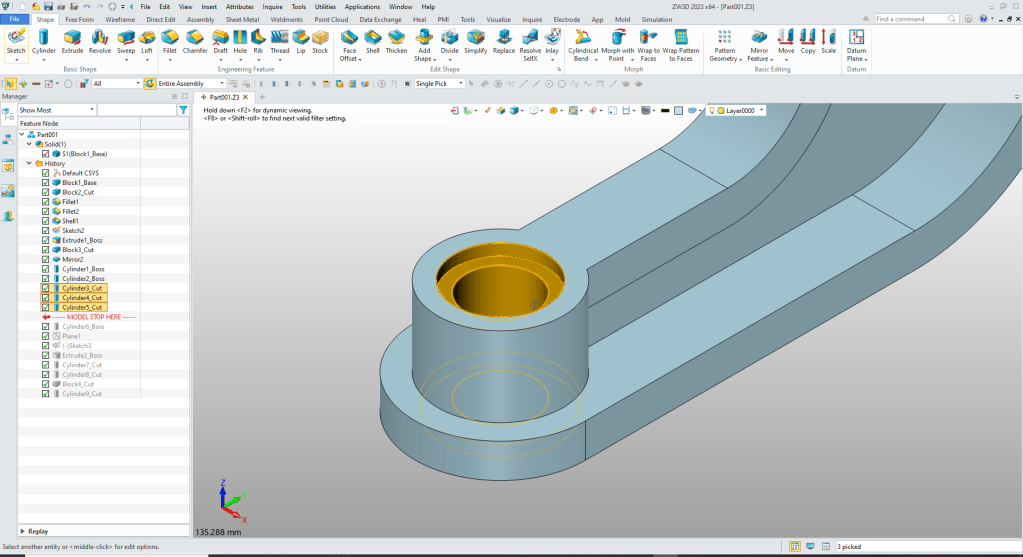
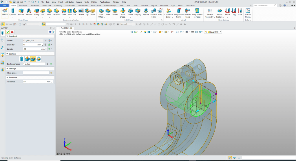
We insert a cylinder for the top boss. We locate and size and add.
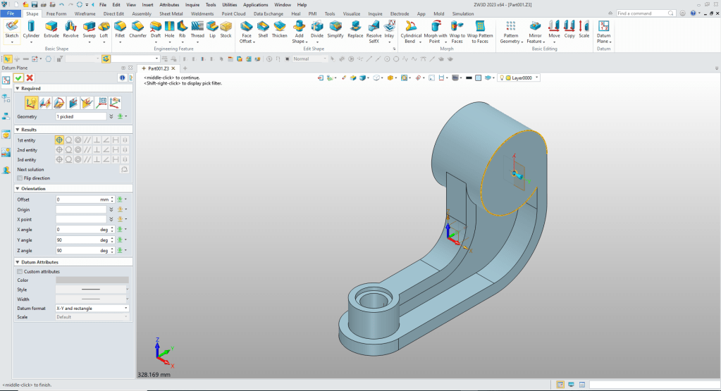
We create a plane at the middle of the boss to create the top feature.
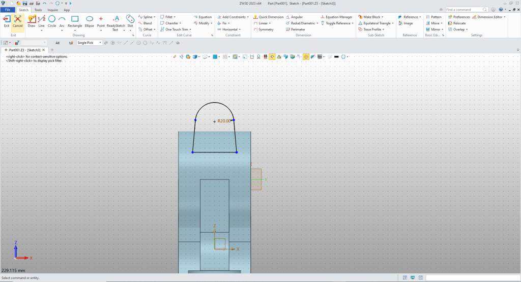
We create the sketch. Notice I don’t use any constraints, I call this StreamLined Sketching.
WE extrude the sketch with the symmetry option and set to add.
We insert two cylinders to create the counterbore and thru hole set to remove.
We insert another cylinder at the center of the boss and it automatically recognizes the center and we size it and set to remove.
We insert another cylinder using the center of the boss, size it and set to remove.
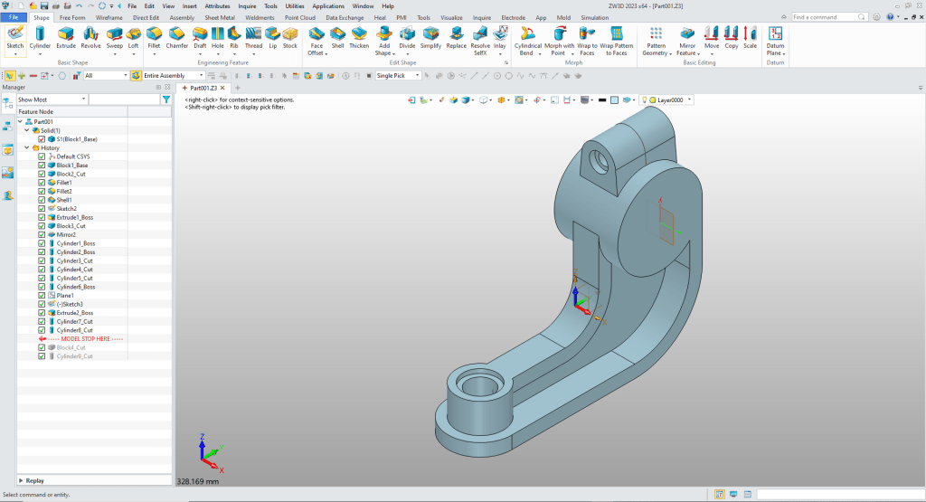
We are done with the part. Using shapes moves the sketch and extrude into one simple step. There were 13 shapes use just in this simple part.
It is very important that you look into how you or your engineers are creating the parts. Streamline Sketching and Feature Based Modeling is easy to learn and implement. It, alone, will increase productivity 10X. Now, ZW3D with its add primitive shapes can increase your productivity another 5X or more with changes! Again, time is money in engineering.
More on Streamline Sketching and Feature Based Modeling.
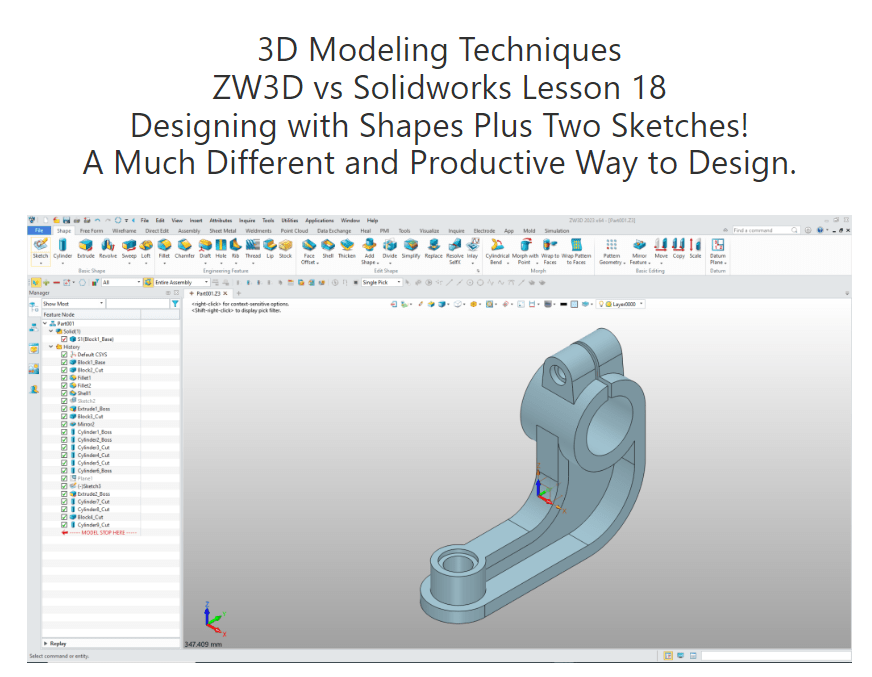
3D Modeling Techniques Defined
To experience this increased level of productivity, please download ZW3D for a 30 day evaluation. Legacy data is no problem, ZW3D can read the native files of all of the popular programs. ZW3D is a great replacement for the subscription only Autodesk and PTC products.
For more information or to download ZW3D
Give me a call if you have any questions. I can set up a skype or gotomeeting to show this part or answer any of your questions on the operation of ZW3D. It truly is the very best conceptual 3D CAD system.
TECH-NET Engineering Services!
We sell and support IronCAD and ZW3D Products and
provide engineering services throughout the USA and Canada!
Why TECH-NET Sells IronCAD and ZW3D
If you are interested in adding professional hybrid modeling capabilities or looking for a new solution to increase your productivity, take some time to download a fully functional 30 day evaluation and play with these packages. Feel free to give me a call if you have any questions or would like an on-line presentation.
For more information or to download IronCAD or ZW3D
Joe Brouwer
206-842-0360
