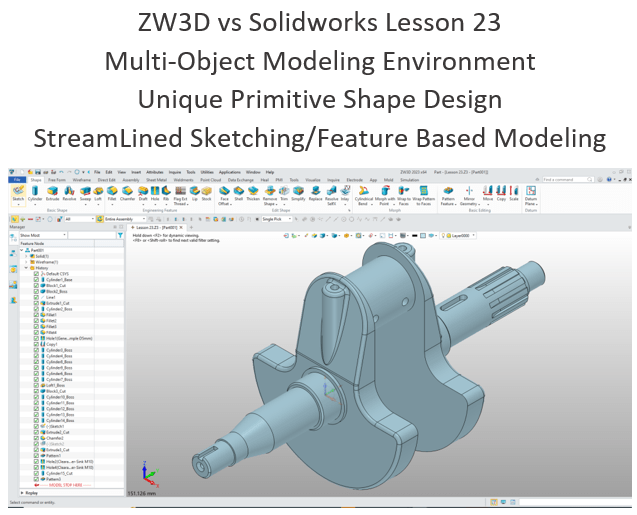
The modeling technique is hugely responsible for the level of productivity. Those of you that are only trained in the sketch, sketch, constrain, constrain world are truly limited by not using the freedom of Streamlined Sketching and Feature Based Design, that is available in even the most Pro/e-ish of CAD systems. If your designers are designing in these very unproductive and time consuming processes it might be time to review your standard design processes. Don’t have any do you?
ZW3D is a sketch based system so it is easy for the major CAD system users to get up to speed fast. But it also has Primitive Shapes available that can eliminate the need to sketch and extrude in many cases.
I saw the following video challenge on linkedin and thought I would give it a try. I actually did it before I watched the video, so I did it a bit differently. This will give you an idea how different and flexible ZW3D is compared to the conventional Solidworks
SolidWorks tutorial for beginners exercise 158
While creating 3D models from drawing is the very best way to learn 3D CAD and maybe some design techniques is does not expose the designer to the design flexibility necessary in product design. ZW3D can be set up one part per file or multi-object which offers incredibly flexible top down design. Creating mating parts is a cruise. But modeling is just one aspect of a well designed productive 3D CAD system.
ZW3D is one the few 3D CAD systems that has integrated drawings, so you can do complete projects or sub-assemblies in one file.
I would do a video, but I really am not good at it. So I will show you step by step. I will try and get IronCAD support to create one. They are very good.
I always create the part before I watch the Solidworks Video, so as to not taint my process. Of course, there are a multitude of ways to create a model. There is no right way, just more productive ways. From what I have seen from these very complicated processes done by the Solidworks Presenters, it is not just limited by the 3D CAD system.
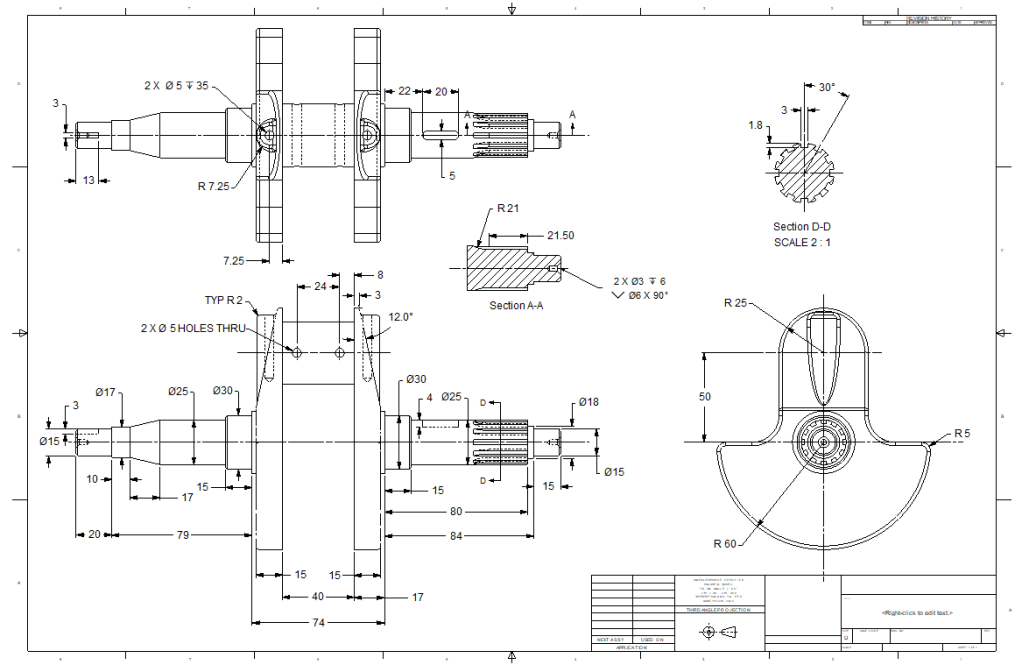
Here is the drawing if you would like to follow along.
Download ZW3D and follow along
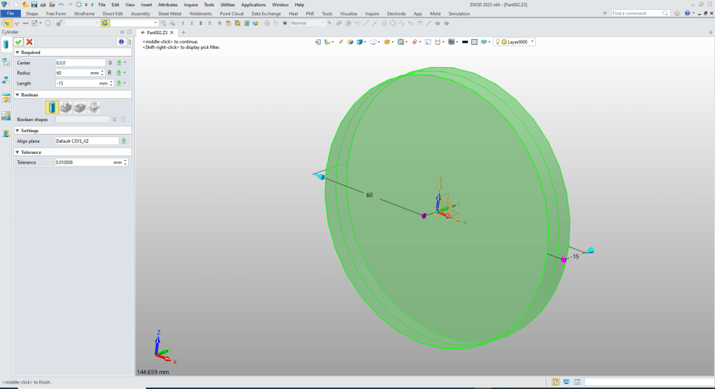
I insert a cylinder and size it.
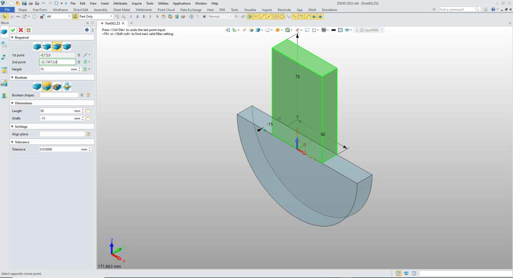
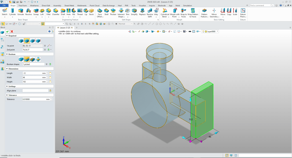
We insert a block to create the bottom of the crank locate at the center of the cylinder, size and set to remove.
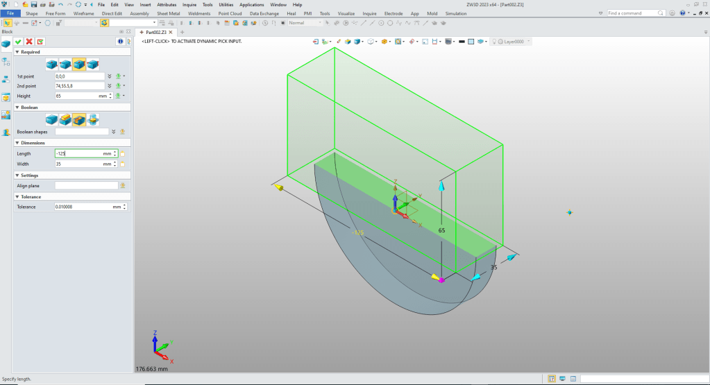
We insert a block, locate
We want to work in 3D as much as we can and avoid sketches. So we create our cut line on the side face. We locate, orientate and set the length.
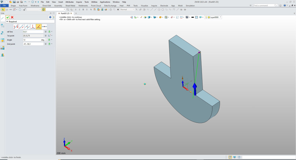
We extrude the line and select the side to remove.

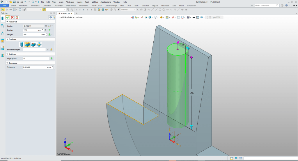
We we will now add the vertical cylinder. We blank the line. We insert a cylinder, locate and size it and set to add.
Now some fillets.
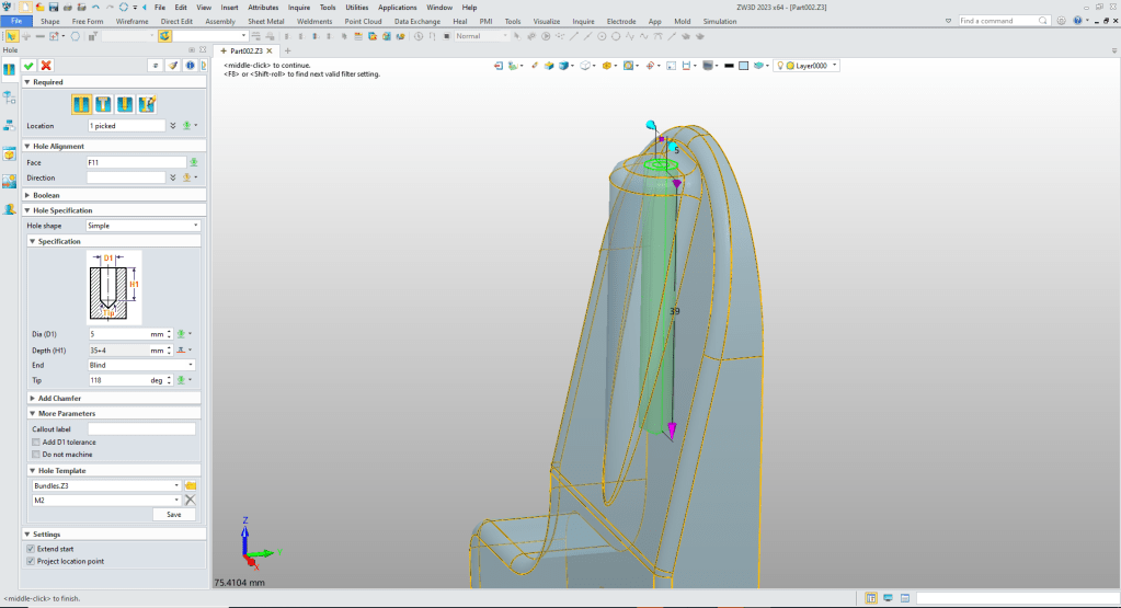
We create the hole with hole tool.
No we need to copy the new shape. We use the rotate copy command.

At this point we have two separate solids. Now we add the bearing shaft and it will become a single shape again. We insert a cylinder at center of top arc, size and set to add.

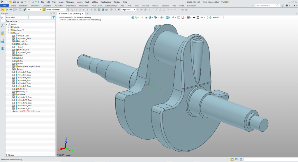
We are now done with the basic crank shape. We now again have a single solid.

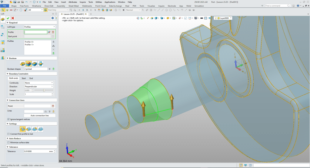
We just insert the cylinders on the near side. It creates two solids. Notice we leave a space between the cylinder for a loft.
Now we will loft the shape and it will take it back to a single solid.
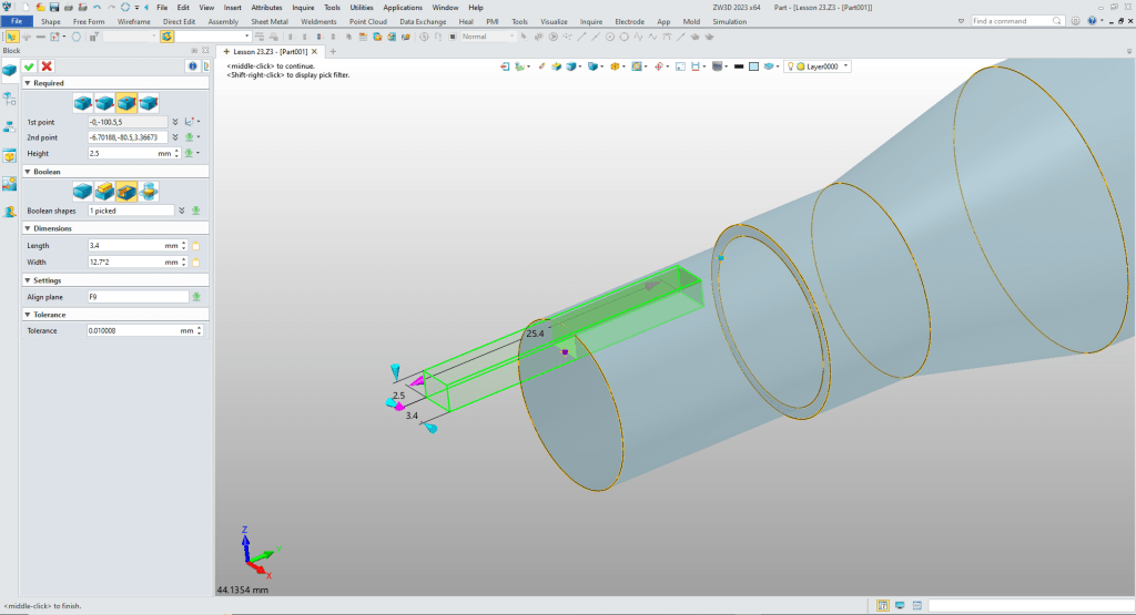
Now for the slot. We insert a block, locate, size and set to remove.
We now add the far side cylinders.
Now for the slot. We will need a sketch. So we create a sketch on the XY Plane.
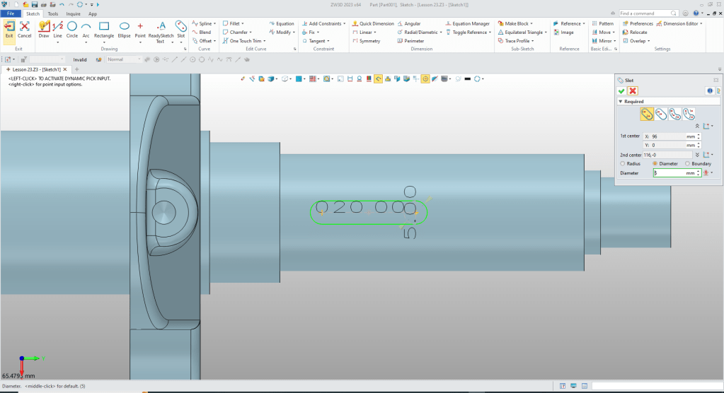
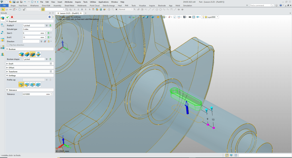
We exit the sketch, extrude the profile.
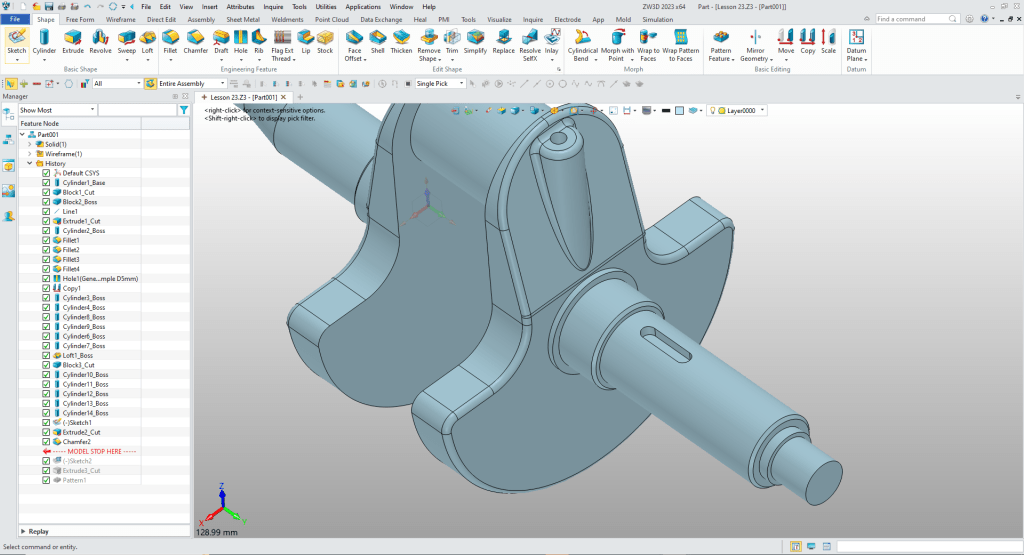
We select the prior chamfer command in the history and move to the end. We now use it to create the two chamfers.

We create a sketch for the spline YZ plane.
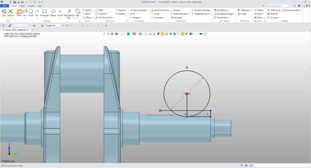
We trim up the sketch. We are using StreamLined sketching.
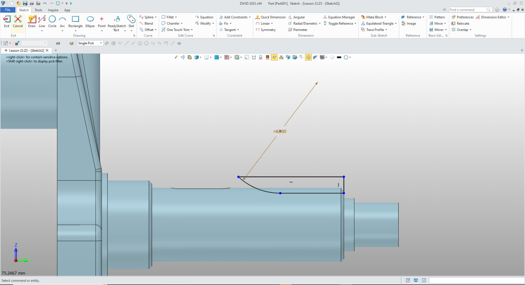
We exit the sketch and extrude the profile

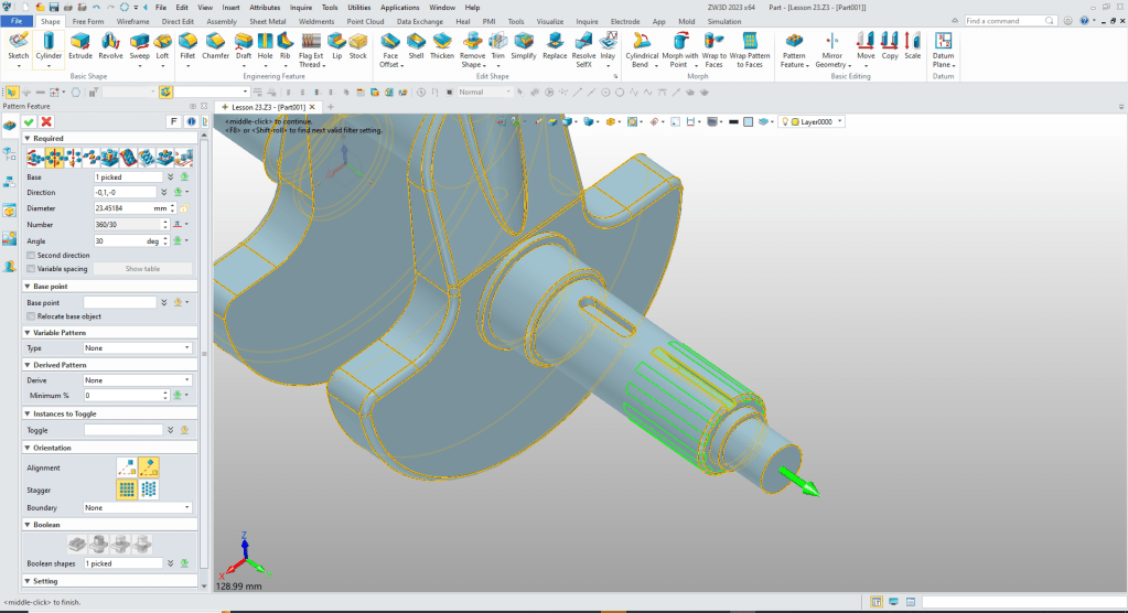
We use the pattern feature command to create the grooves.
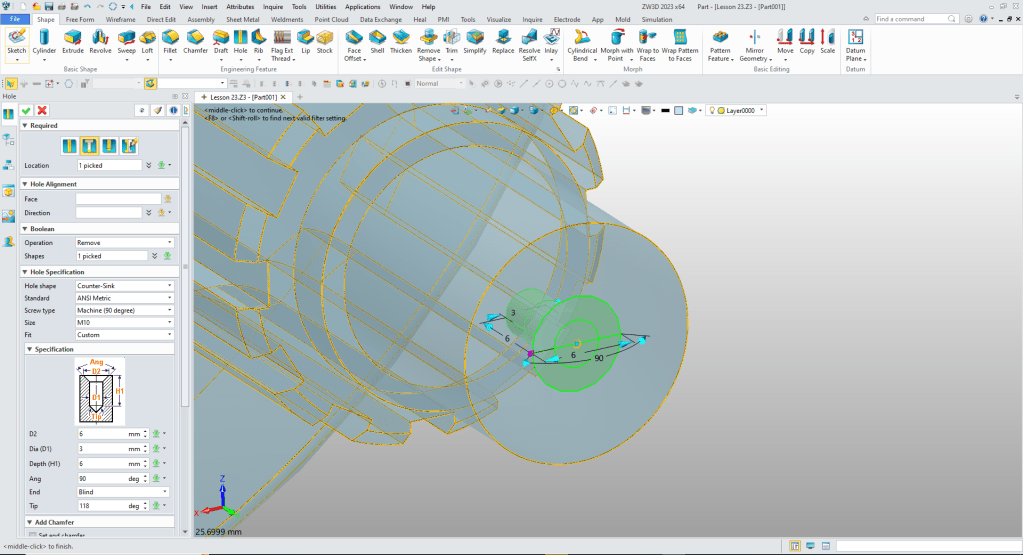
Now for the end holes. We use the hole command and put the two holes in the ends.
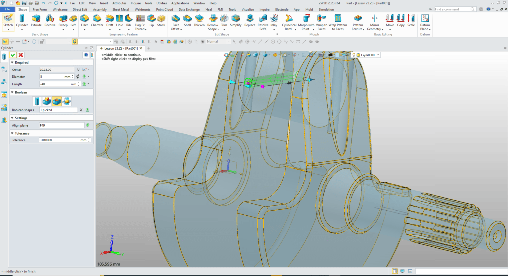
Now for the hole through the bearing shaft. We insert a cylinder, locate and size.
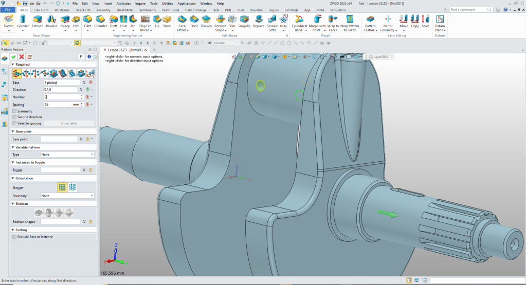
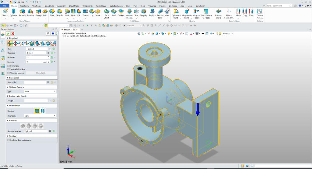
Now we pattern the hole.
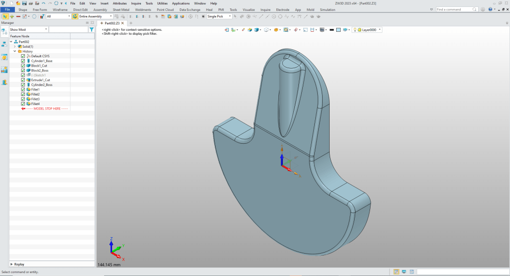
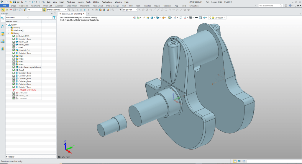
We are done with the part.

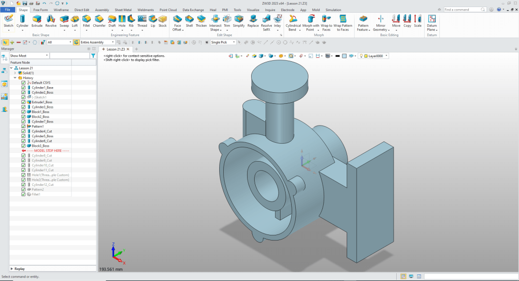
We are done with the model.
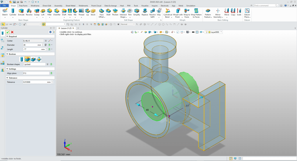
Now we insert a cylinder on the center of the large cylinder. ZW3D recognizes centers, midpoints and corners to place features. We then size and set to remove.
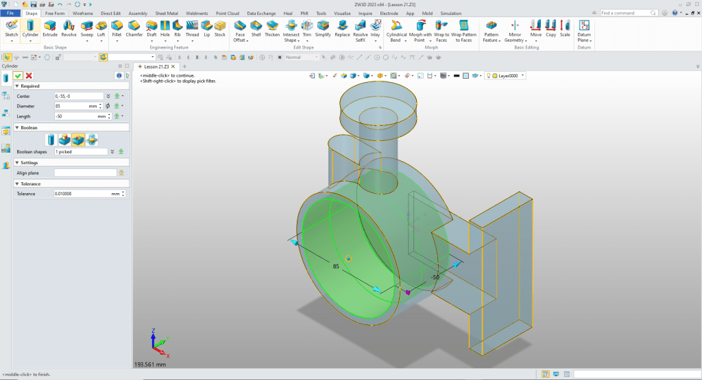
We insert a cylinder at the center of the large cylinder again, locate, size and set to add.
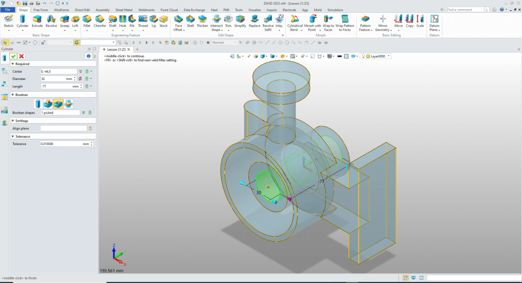
We insert a cylinder to create the center cut at the center of the existing boss size and set to remove. The length is still in the dialog box.
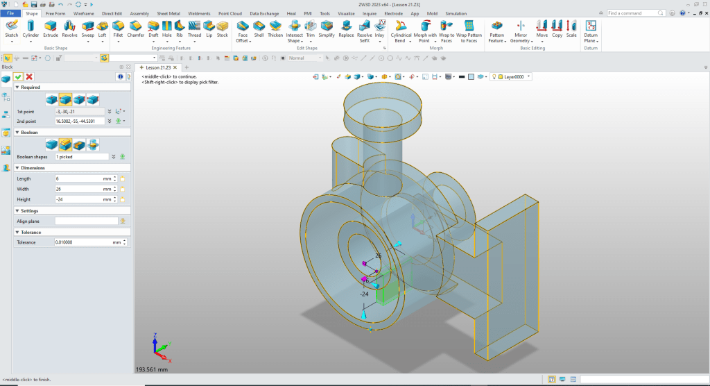
Now for the bottom rib. We locate the origin at the bottom quadrant of the inside boss, locate, size and set to add.
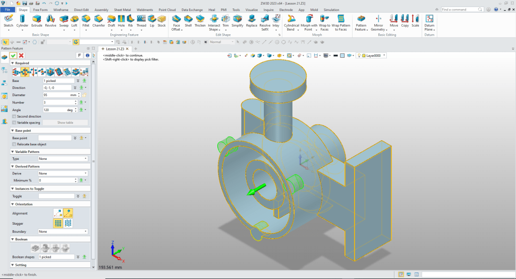
We create the mounting tab at the lower quadrant point of the outside radius of the large cylinder. We then pattern them.
We should have put the bosses at a early step. But all we have to do is move them before of the inner cut.
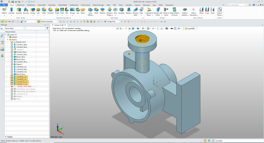
We add the 4 holes by inserting cylinders, locating, sizing and set to remove.
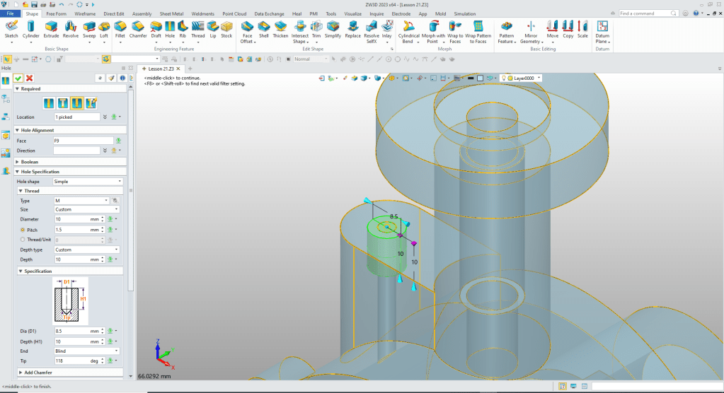
We have four thread holes. ZW3d has a wonderful hole wizard to define threaded and other type holes.
We will put the M10 threaded hole in first. We select metric, the holes size, select thread and set the depth.
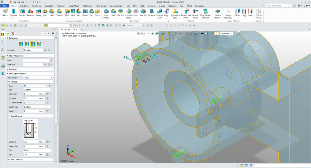
Now for the mounting tab holes. We just locate them at the center of the mounting tabs.
Two more holes. We insert a cylinder at the top locate, size and set to remove. We select the pattern feature command to create the lower hole.
Now for the fillets and we are done.
It is very important that you look into how you or your engineers are creating the parts. Streamline Sketching and Feature Based Modeling is easy to learn and implement. It, alone, will increase productivity 10X. Now, ZW3D with its add primitive shapes can increase your productivity another 5X or more with changes! Again, time is money in engineering.
More on Streamline Sketching and Feature Based Modeling.
3D Modeling Techniques Defined
To experience this increased level of productivity, please download ZW3D for a 30 day evaluation. Legacy data is no problem, ZW3D can read the native files of all of the popular programs. ZW3D is a great replacement for the subscription only Autodesk and PTC products.
For more information or to download ZW3D
Give me a call if you have any questions. I can set up a skype or gotomeeting to show this part or answer any of your questions on the operation of ZW3D. It truly is the very best conceptual 3D CAD system.
TECH-NET Engineering Services!
We sell and support IronCAD and ZW3D Products and
provide engineering services throughout the USA and Canada!
Why TECH-NET Sells IronCAD and ZW3D
If you are interested in adding professional hybrid modeling capabilities or looking for a new solution to increase your productivity, take some time to download a fully functional 30 day evaluation and play with these packages. Feel free to give me a call if you have any questions or would like an on-line presentation.
For more information or to download IronCAD or ZW3D
Joe Brouwer
206-842-0360
