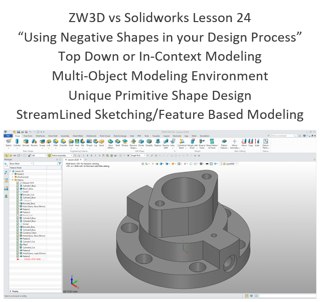
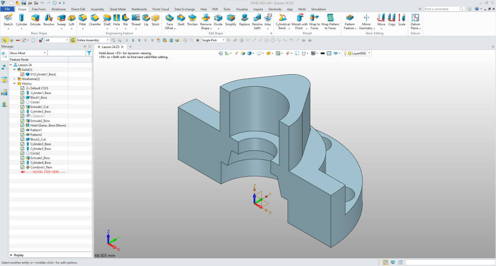
What is the advantage designing with shapes?
Using shapes eliminates the need to create a sketch and extrude. The above part has 14 shapes and 2 sketches. This is a simple part and we have eliminated 14 constrained sketches and 14 extrusions. Imagine a complex part. Give this concept a try today.
The modeling technique is hugely responsible for the level of productivity. Those of you that are only trained in the sketch, sketch, constrain, constrain world are truly limited by not using the freedom of Streamlined Sketching and Feature Based Design, that is available in even the most Pro/e-ish of CAD systems. If your designers are designing in these very unproductive and time consuming processes it might be time to review your standard design processes. Don’t have any do you?
ZW3D is a sketch based system so it is easy for the major CAD system users to get up to speed fast. But it also has Primitive Shapes available that can eliminate the need to sketch and extrude in many cases.
I saw the following video challenge on linkedin and thought I would give it a try. I actually did it before I watched the video, so I did it a bit differently. This will give you an idea how different and flexible ZW3D is compared to the conventional Solidworks
Exercise in Solidworks
ZW3D vs Solidworks
While creating 3D models from drawing is the very best way to learn 3D CAD and maybe some design techniques is does not expose the designer to the design flexibility necessary in product design. ZW3D can be set up one part per file or multi-object which offers incredibly flexible top down design. Creating mating parts is a cruise. But modeling is just one aspect of a well designed productive 3D CAD system.
ZW3D is one the few 3D CAD systems that has integrated drawings, so you can do complete projects or sub-assemblies in one file.
I would do a video, but I really am not good at it. So I will show you step by step. I will try and get IronCAD support to create one. They are very good.
I always create the part before I watch the Solidworks Video, so as to not taint my process. Of course, there are a multitude of ways to create a model. There is no right way, just more productive ways. From what I have seen from these very complicated processes done by the Solidworks Presenters, it is not just limited by the 3D CAD system.
Here is the drawing if you would like to follow along.
Download ZW3D and follow along

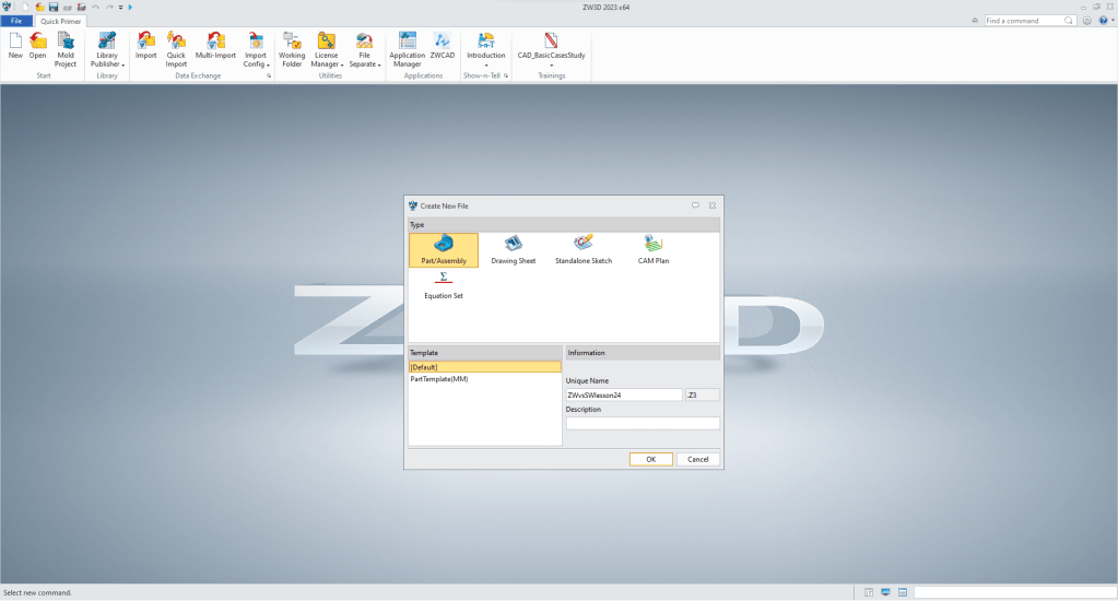
We create a new file and name it.
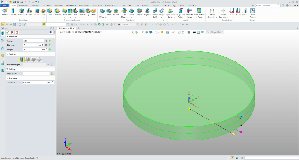
We insert a cylinder at X0Y0Z0 and size it.
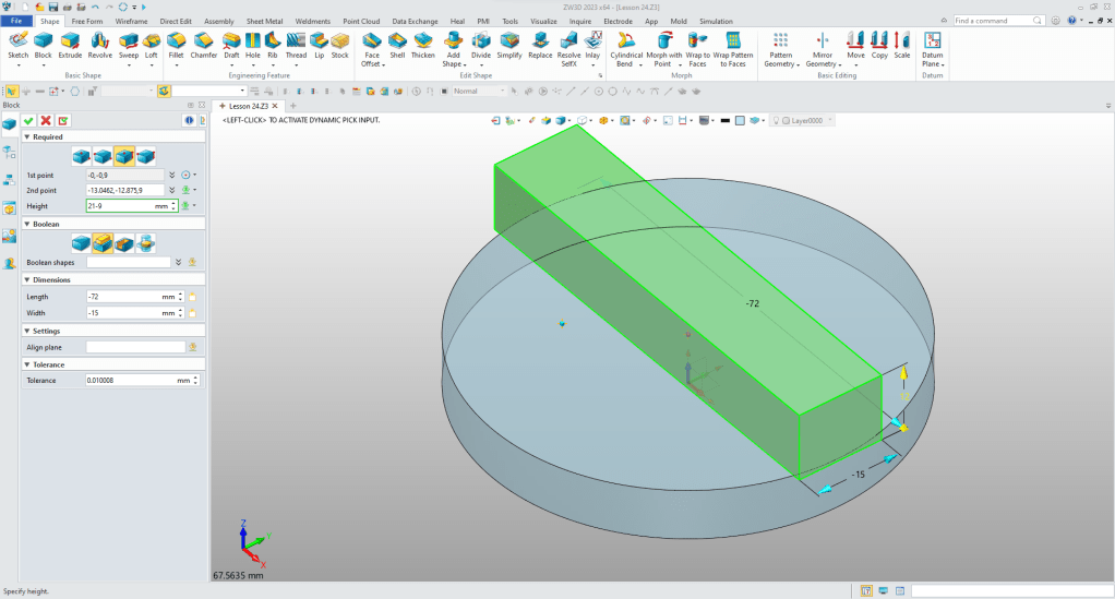
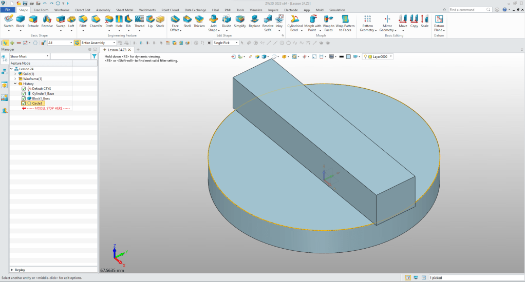
We are going to design with primitive shape. So we insert a block at the center of the cylinder and size it.
Now we have to match the ends to the cylinder. We now have to create some wireframe to trim the faces.
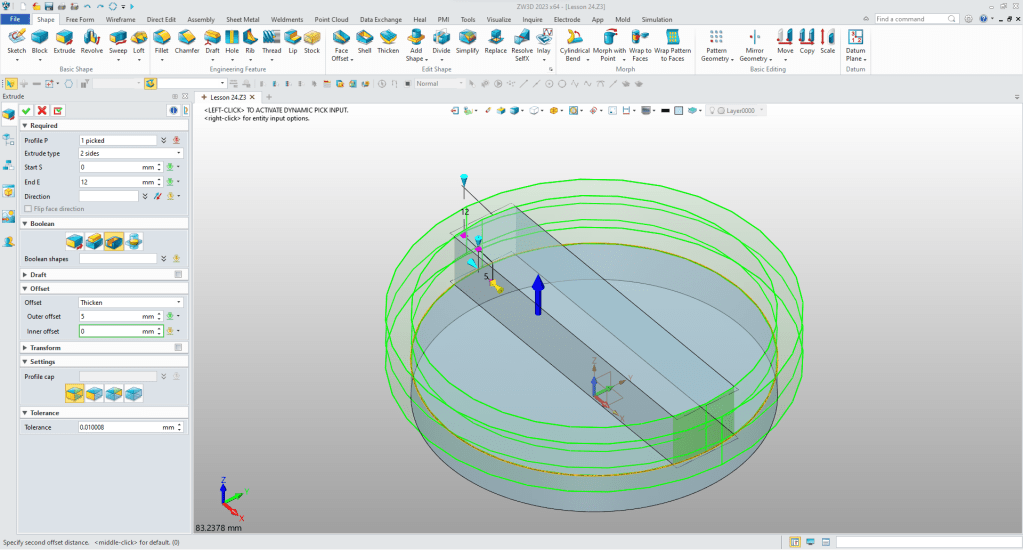
We select extrude and select the circle and set the offset and set to remove. I like not having to make a sketch when doing such simple functions.
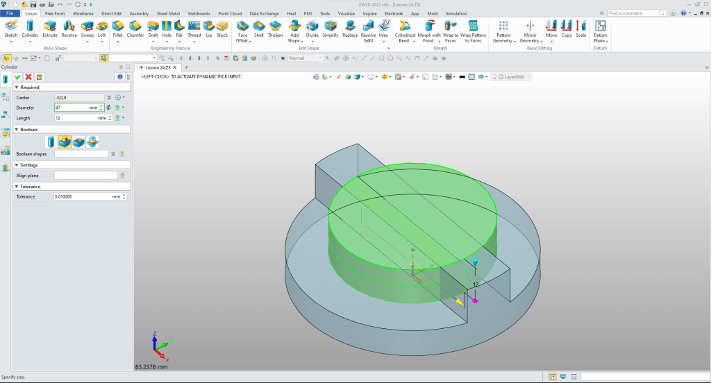
We insert another at the center of the top of the existing cylinder, size it and set it to add.
Now for the flange. We will create a sketch and using StreamLined Sketching we create the basic entities.
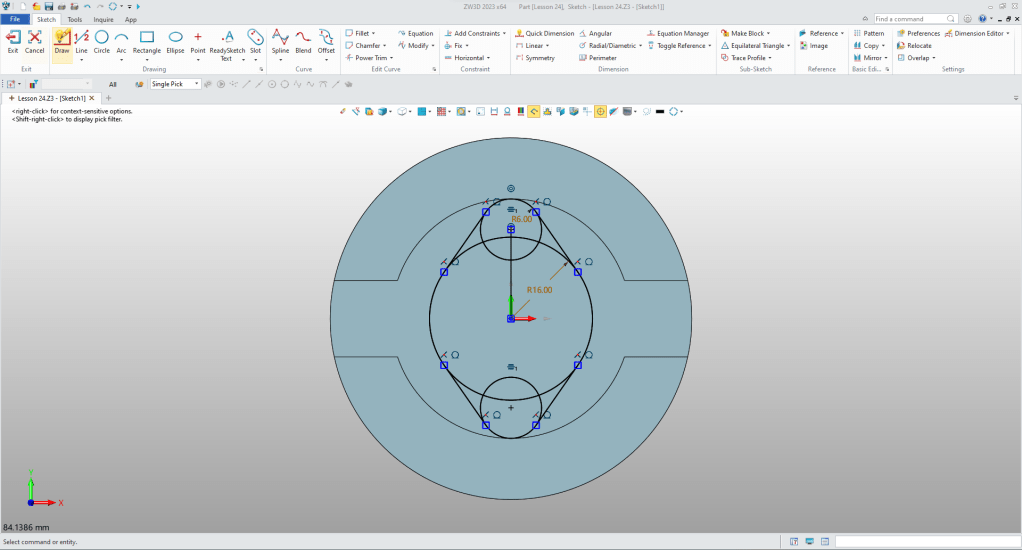
Now we trim/ext or delete the entities to create a good profile. We exit and extrude the profile to correct height and set to add.

Using the Create Hole feature we create the counterbored hole and locate it.
Using the pattern copy tool we create the rest of the holes.

We are going to some thing quite a bit different we are going to create a negative shape. Now we could sketch the internal shape, but we are doing feature based modeling with minimized sketching.
Creating Internal Shapes with Boolean Operations
We are going to do something quite different. We are going to design a positive shape and Boolean subtract it to create an internal feature.
Many times there are internal features that would be much easier if they were positive shapes. Here is an example of that type of design.
It is from this article.
Reverse Engineering 2015 AK-47 Project
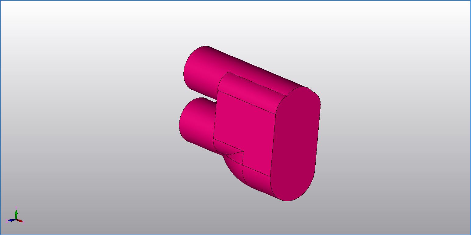
Sometimes it is easier to create a positive part and Boolean subtract it than struggling to design it inside the existing part. Here is the cavity in the back of the stock before subtracting it.
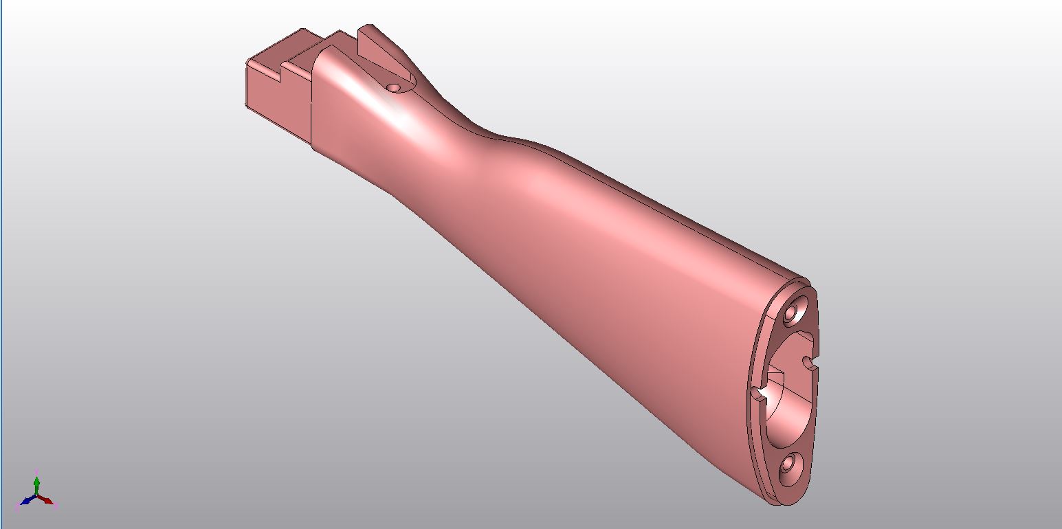
Here is the completed part. You can see that the shape is subtracted.
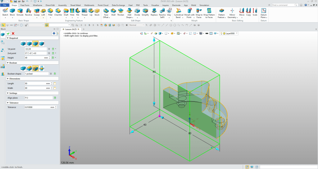
We insert a block, size it and set it to remove for ease of modeling.
We insert a cylinder, locate it, size it and set to independant part. We will set the color for clarity.

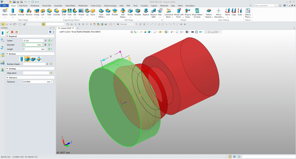
We blank the original shape. We add another cylinder using the bottom center of the new cylinder, size it and set it to add.

We create a wireframe circle using the bottom center of the new cylinder.

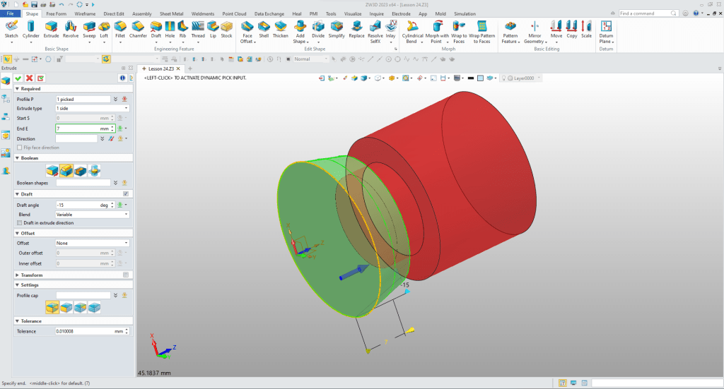
Now we extrude the circle with draft to the correct height.
Now for the bottom cylinder, we locate it at the bottom of the new shape, size it and set to add.
We unblank the other shape and we notice a discrepancy. You get this many times when turning at drawing into a 3D model.
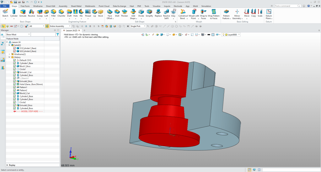
I quickly see that the flange on the top should have been 18mm. I edit the shape and since I used the center on the top of the flange evertything lines up.

We now use remove a shape to create our cavity.
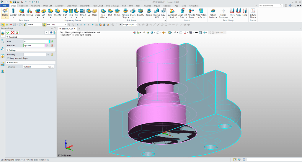
Now we have our cavity removed. We blank the wireframe circle and set the color.
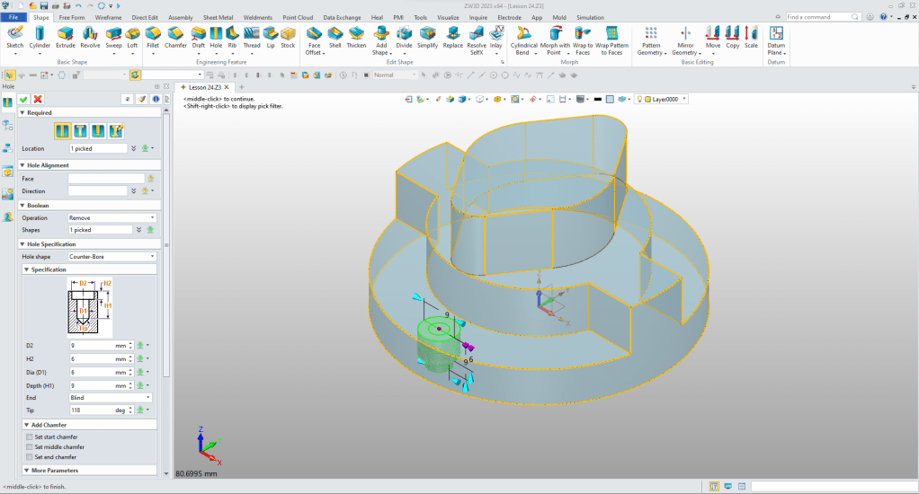
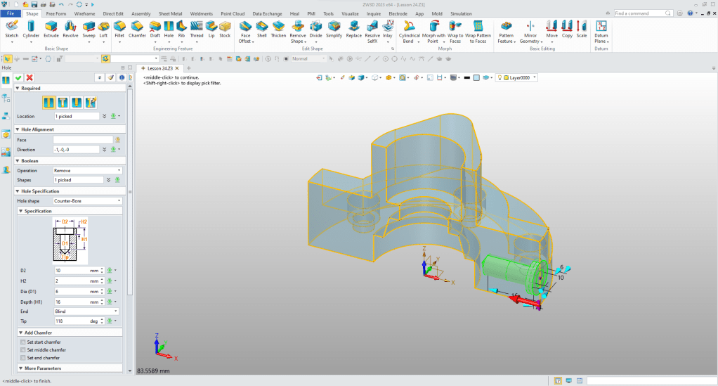
We create the side counter bored hole.
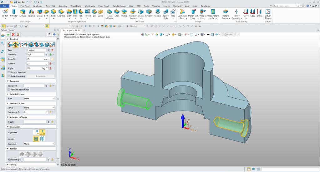
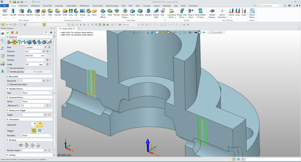
Using the pattern feature command we create the other hole.
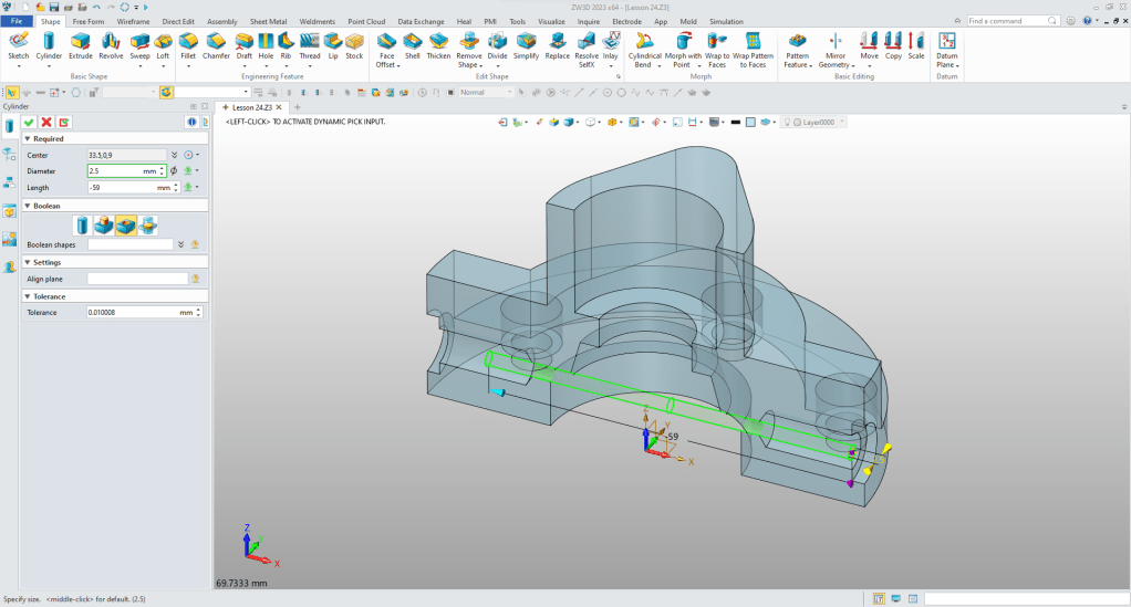
now for the hole through. We instert a cylinder, locate in on the bottom of the counter bored hole, size it and set it to remove.
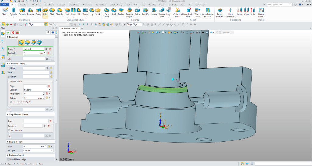
We now put in the fillet.
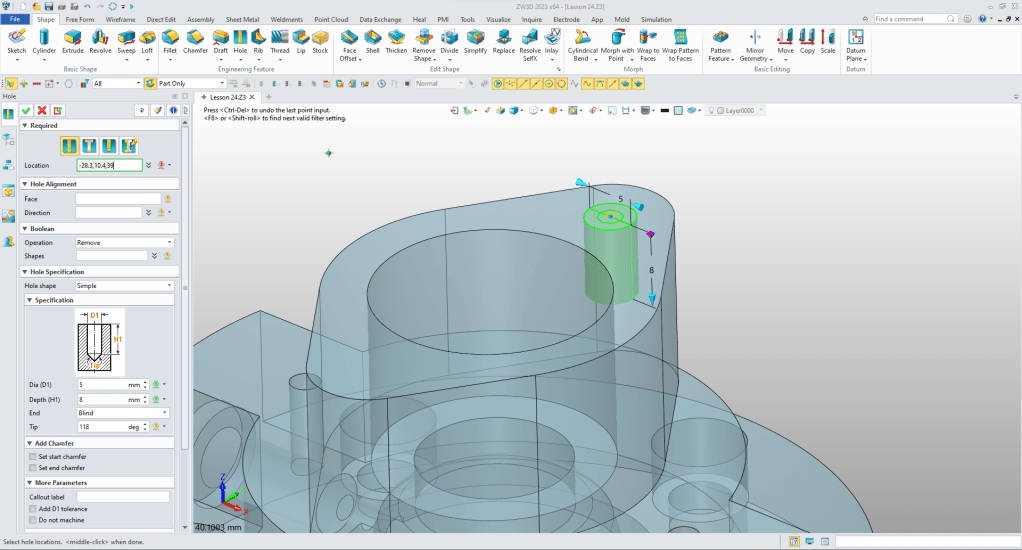
Now for the small holes. We will insert a cylinder, locate it, size it and set to remove.

We pattern copy it.
Now for the two flange holes. Using the hole tool we set it to symple and use the center of the radius to locate and size it. We suppress the block cut.
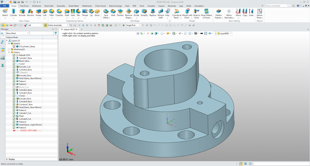
Again we use the pattern copy to create the other hole. And we are done with the model.
It is very important that you look into how you or your engineers are creating the parts. Streamline Sketching and Feature Based Modeling is easy to learn and implement. It, alone, will increase productivity 10X. Now, IronCAD with its unique integrated history/direct edit functionality can increase your productivity another 5X or more with changes! Again, time is money in engineering.
More on Streamline Sketching and Feature Based Modeling.
3D Modeling Techniques Defined
To experience this increased level of productivity, please download ZW3D for a 30 day evaluation. Legacy data is no problem, ZW3D can read the native files of all of the popular programs. ZW3D is a great replacement for the subscription only Autodesk and PTC products.
For more information or to download ZW3D
Give me a call if you have any questions. I can set up a skype or gotomeeting to show this part or answer any of your questions on the operation of IronCAD. It truly is the very best conceptual 3D CAD system.
TECH-NET Engineering Services!
We sell and support IronCAD and ZW3D Products and
provide engineering services throughout the USA and Canada!
Why TECH-NET Sells IronCAD and ZW3D
If you are interested in adding professional hybrid modeling capabilities or looking for a new solution to increase your productivity, take some time to download a fully functional 30 day evaluation and play with these packages. Feel free to give me a call if you have any questions or would like an on-line presentation.
For more information or to download IronCAD or ZW3D
Joe Brouwer
206-842-0360
