Please go to here to see the other lessons.
ZW3D vs Solidworks Assembly Lesson 19
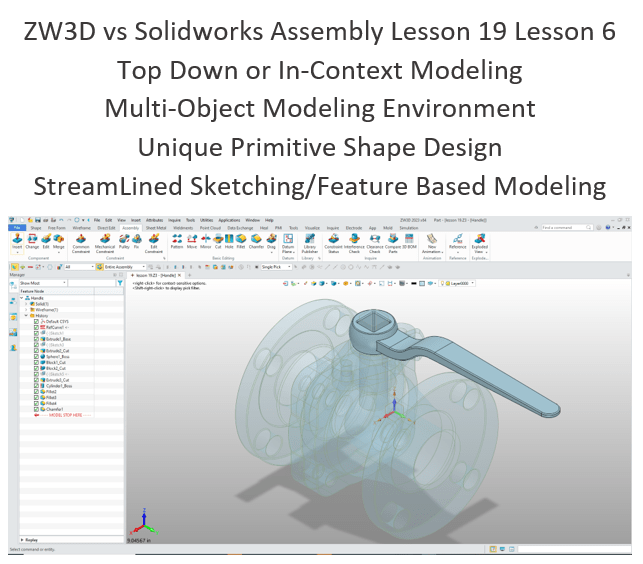
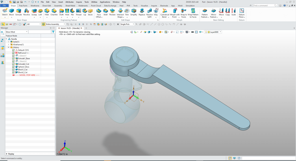
What is the advantage designing with shapes?
Using shapes eliminates the need to create a sketch and extrude. The above part has 14 shapes and 2 sketches. This is a simple part and we have eliminated 14 constrained sketches and 14 extrusions. Imagine a complex part. Give this concept a try today.
Design of Water Control Valve in Solidworks
ZW3D vs Solidworks
While creating 3D models from drawing is the very best way to learn 3D CAD and maybe some design techniques is does not expose the designer to the design flexibility necessary in product design. IronCAD is all top down due to the single model environment. Creating mating parts is a cruise. But modeling is just one aspect of this well designed productive 3D CAD system.
I like to show step by step lessons So you can see the commands being used.
I always create the part before I watch the Video, so as to not taint my process. Of course, there are a multitude of ways to create a model. There is no right way, just more productive ways. From what I have seen from these very complicated processes done by the Solidworks Presenters, it is not just limited by the 3D CAD system.
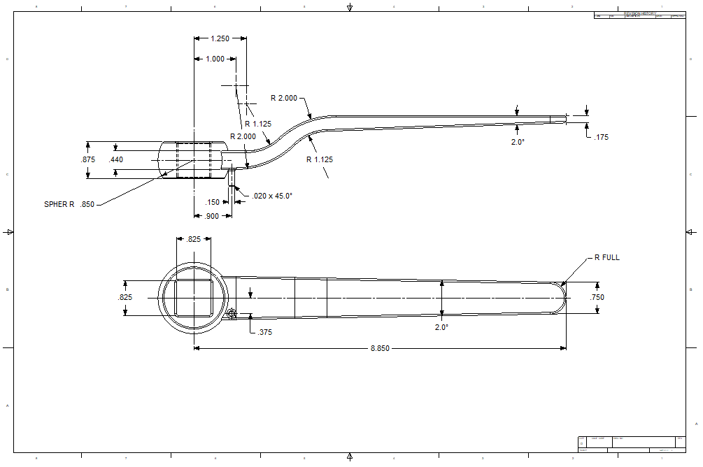
Here is the drawing if you would like to follow along.
Download ZW3D and follow along
We use the “New to Insert” command under the the Control Valve Assembly and name the part Lock Lever. We edit or activate the part. This how we design top down.
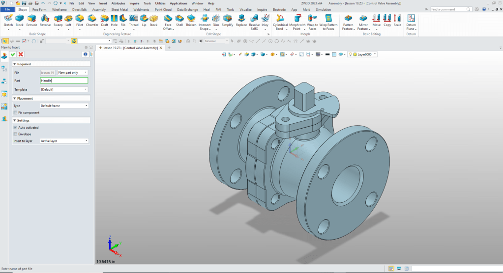
It automatically goes to the edit part mode, which allows top-down modeling.

We will only show the mating part.

We go to the assembly mode. We create reference entity.
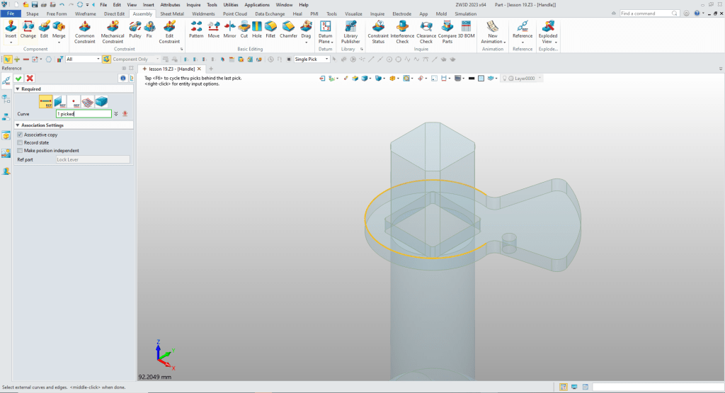
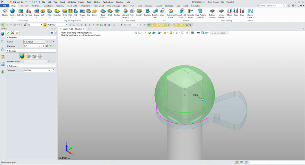
We insert a primitive sphere size and locate it. It is automatically set to standalone.
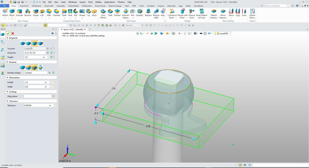
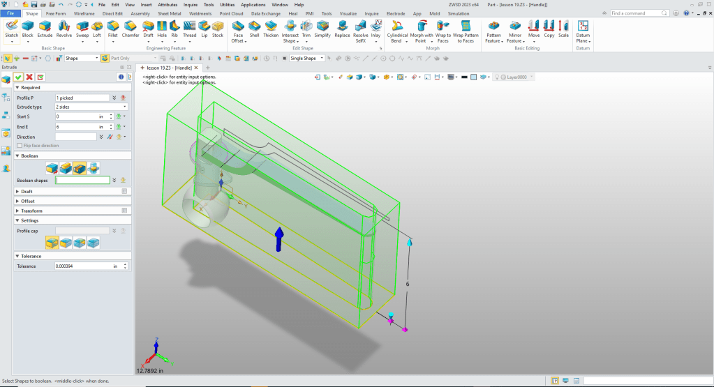
No we will drop a primitive block located, size it and set it to remove, do it again for the bottom.
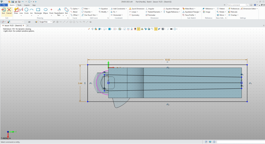
Now for the handle. We create a sketch on Y-Z plane. We use what I call StreamLined Sketching. No constraints.
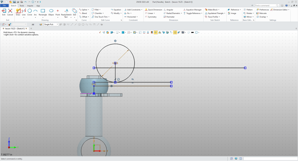
We clean up the sketch, leaving a few construction lines.

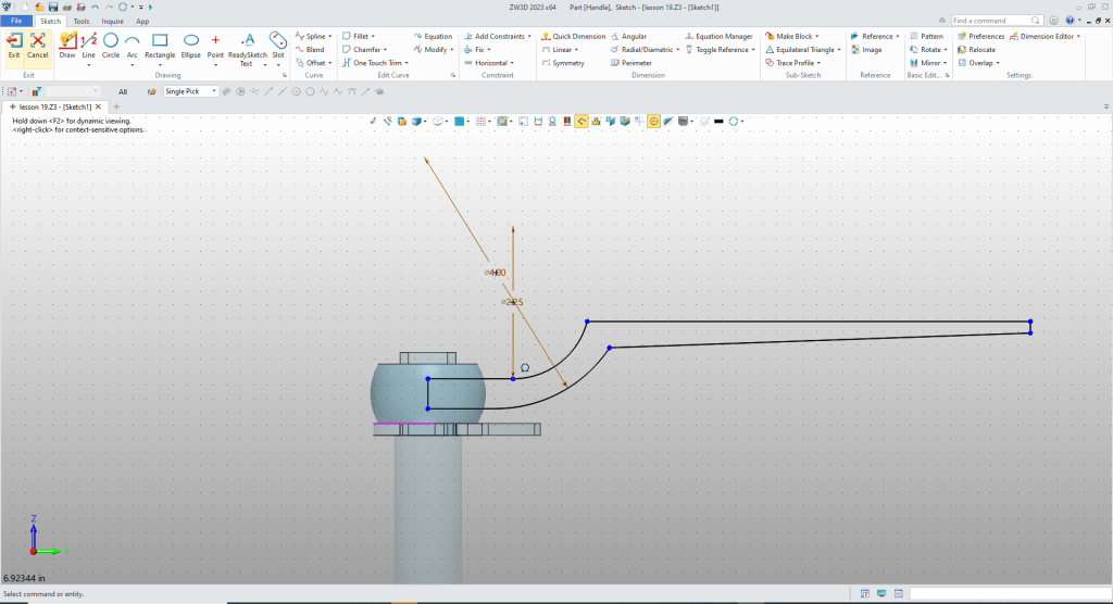
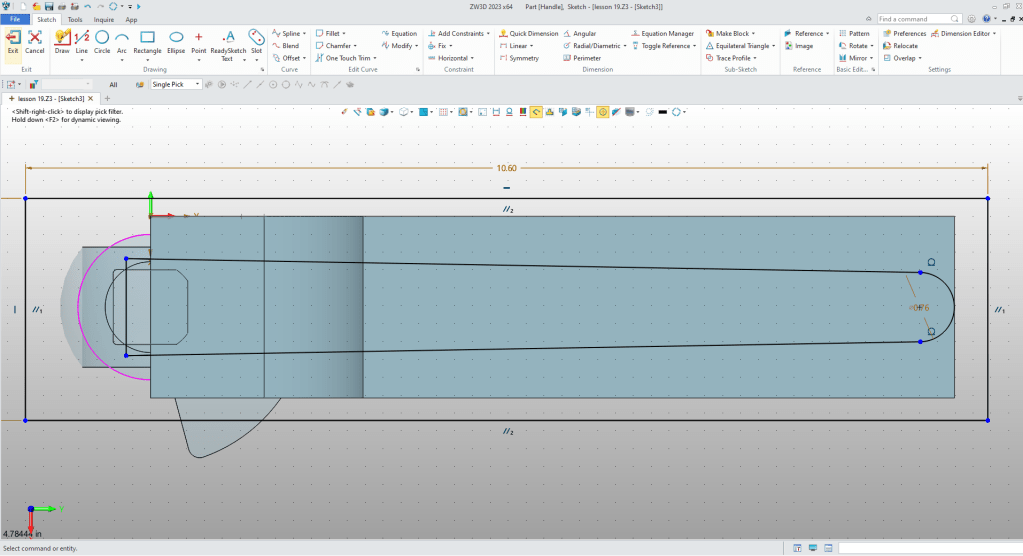
Here are the graphics necessary to create the bottom of the handle.

We clean up the sketch and complete it.
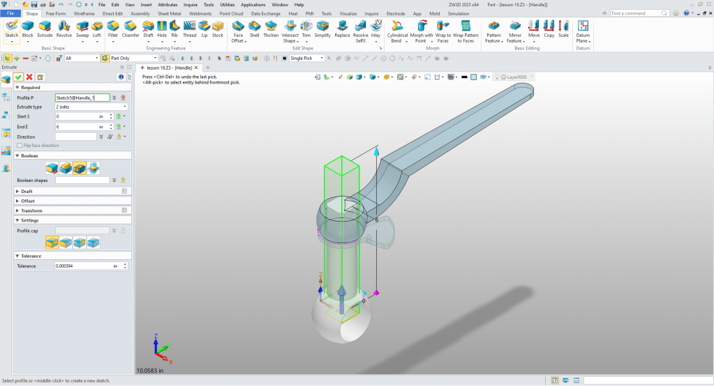
We exit the sketch and extrude to an arbitrary width.
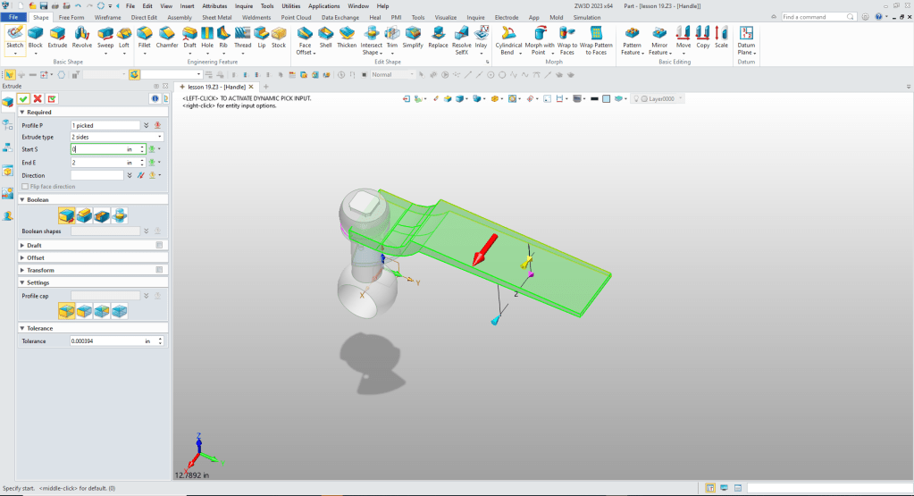
I quickly realize I did not do my design intent. So we will move the sketch and extrusion above the sphere. It makes the new extrusion a standalone shape, which means we have to set the sphere to add.

We will move the new sketch to below the new extrusion. Again we use StreamLined Sketching, no constraints.
We clean up the sketch.
We exit the sketch and extrude and set to remove.
We now move the history to the bottom.
Now for the square hole. We create a sketch on the X-Y plane. The graphics from the mating parts are available for construction of the sketch. We create a line between the two midpoints and create a center rectangle and size it.

We delete the construction line and exit the sketch and create the extrusion size and set to remove.
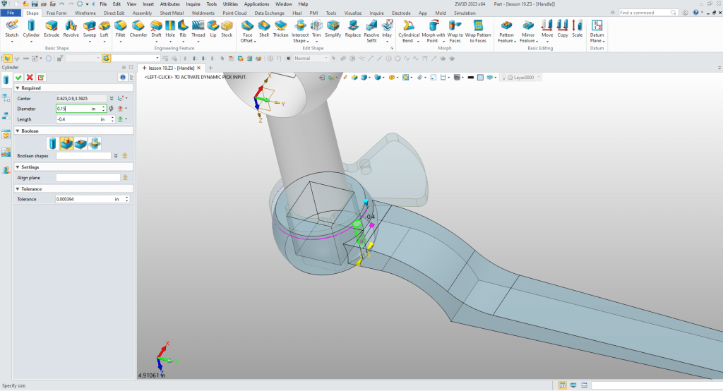
Now for the locking pin. We insert a cylinder locate, size and set it to add.
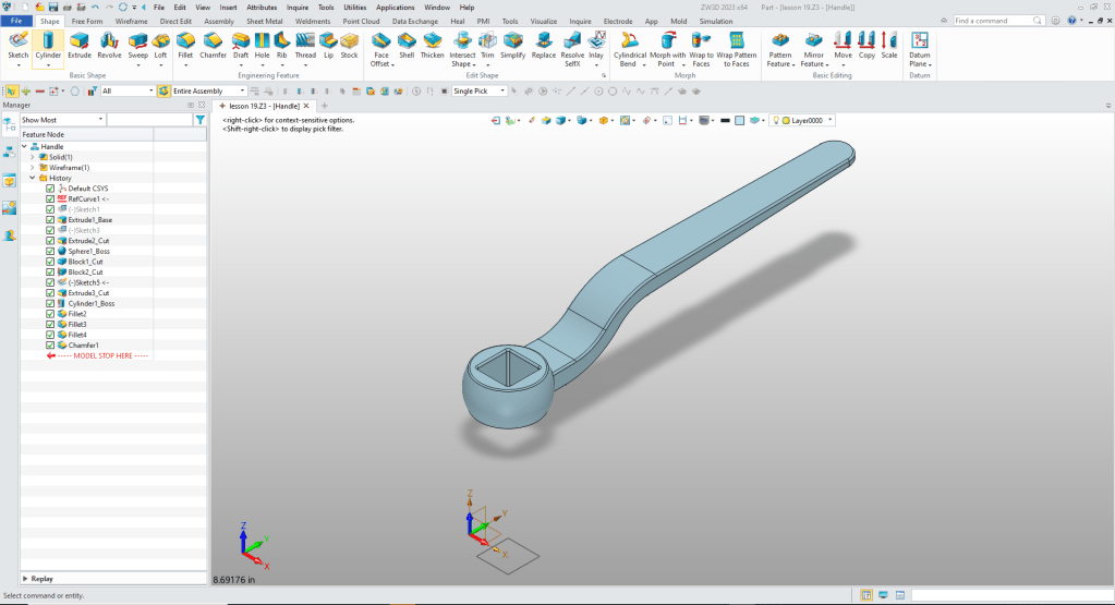
Now for the fillets and chamfer and we are done.
Please go to here to see the other lessons.
ZW3D vs Solidworks Assembly Lesson 19
It is very important that you look into how you or your engineers are creating the parts. Streamline Sketching and Feature Based Modeling is easy to learn and implement. It, alone, will increase productivity 10X. Now, IronCAD with its unique integrated history/direct edit functionality can increase your productivity another 5X or more with changes! Again, time is money in engineering.
More on Streamline Sketching and Feature Based Modeling.
3D Modeling Techniques Defined
To experience this increased level of productivity, please download ZW3D for a 30 day evaluation. Legacy data is no problem, ZW3D can read the native files of all of the popular programs. ZW3D is a great replacement for the subscription only Autodesk and PTC products.
For more information or to download ZW3D
Give me a call if you have any questions. I can set up a skype or gotomeeting to show this part or answer any of your questions on the operation of IronCAD. It truly is the very best conceptual 3D CAD system.
TECH-NET Engineering Services!
We sell and support IronCAD and ZW3D Products and
provide engineering services throughout the USA and Canada!
Why TECH-NET Sells IronCAD and ZW3D
If you are interested in adding professional hybrid modeling capabilities or looking for a new solution to increase your productivity, take some time to download a fully functional 30 day evaluation and play with these packages. Feel free to give me a call if you have any questions or would like an on-line presentation.
For more information or to download IronCAD or ZW3D
Joe Brouwer
206-842-0360
