Please go to here to see the other lessons.
ZW3D vs Solidworks Assembly Lesson 22
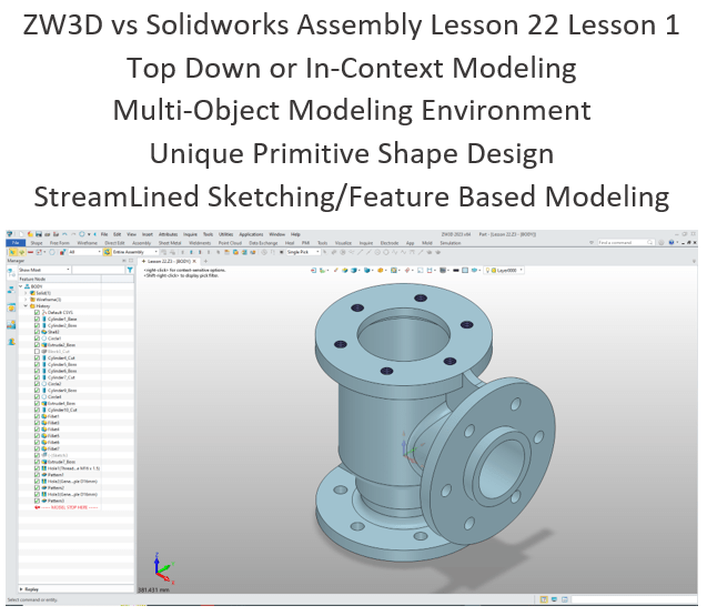
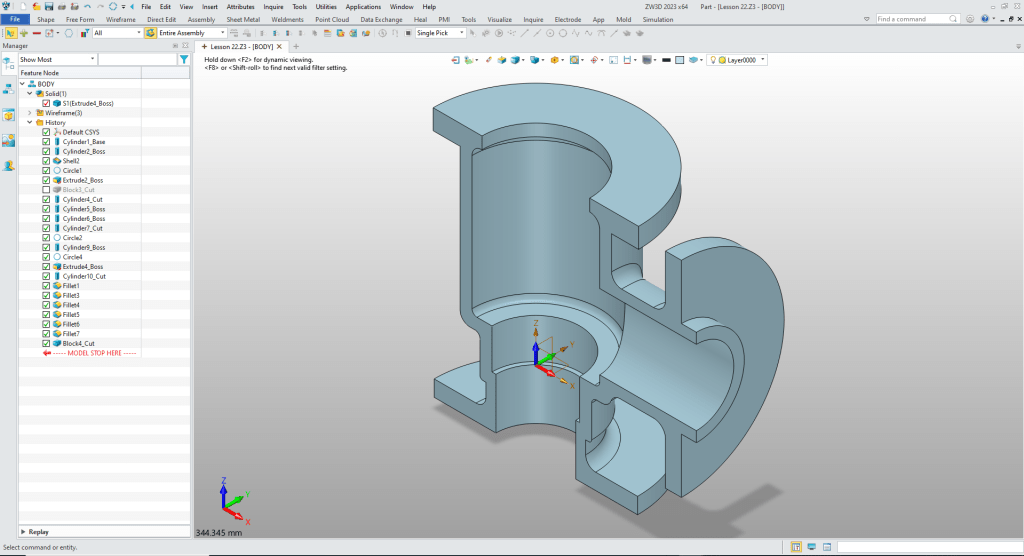
What is the advantage designing with shapes?
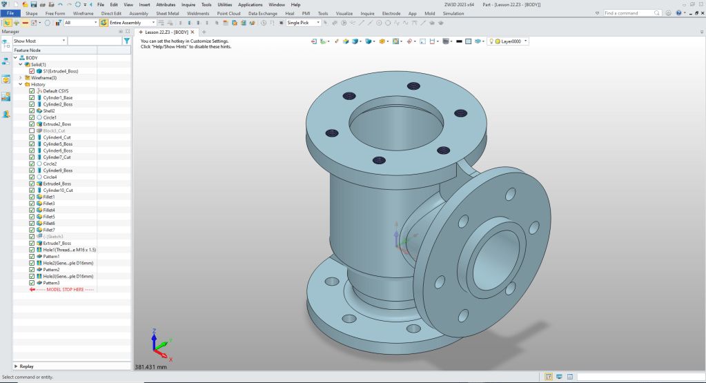
Using shapes eliminates the need to create a sketch and extrude. The above part has 14 shapes and 2 sketches. This is a simple part and we have eliminated 14 constrained sketches and 14 extrusions. Imagine a complex part. Give this concept a try today.
Design of Feed check Valve in Solidworks
ZW3D vs Solidworks
While creating 3D models from drawing is the very best way to learn 3D CAD and maybe some design techniques is does not expose the designer to the design flexibility necessary in product design. IronCAD is all top down due to the single model environment. Creating mating parts is a cruise. But modeling is just one aspect of this well designed productive 3D CAD system.
I like to show step by step lessons So you can see the commands being used.
I always create the part before I watch the Video, so as to not taint my process. Of course, there are a multitude of ways to create a model. There is no right way, just more productive ways. From what I have seen from these very complicated processes done by the Solidworks Presenters, it is not just limited by the 3D CAD system.
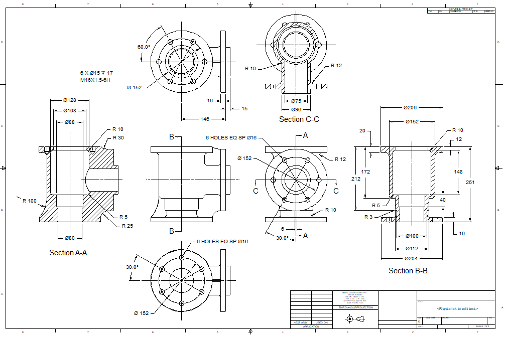
Here is the drawing if you would like to follow along.
Download ZW3D and follow along
ZW3D is a multi-Object environment. Which means all of the parts can reside in the same file. This is different than a single model environment were When you download ZW3D make sure you set this in option.
At the top of the screen will be small arrow pointing to the right. Select it and a menu will open you go Utilities>Configurations and unselect the “One Object per File (New Files)”

This is one of ZW3D most flexible features and should be made known. But ZW3D is focused on all of the popular program that have part, assembly and drawing files. If you prefer working that way ZW3D offers the option. But for his exercise we will work in the multi-object environment.
We will now set up ZW3D to do this assembly.
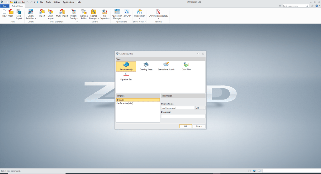
We bring up a new file, we have set the units to millimeters.
We name the part “Feed Check Valve”
We will now select “New to Insert” and name the part “BODY”
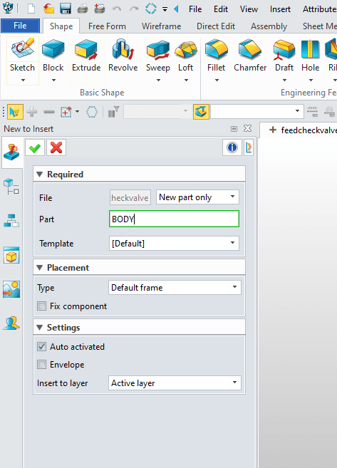
Now we can start creating our model.
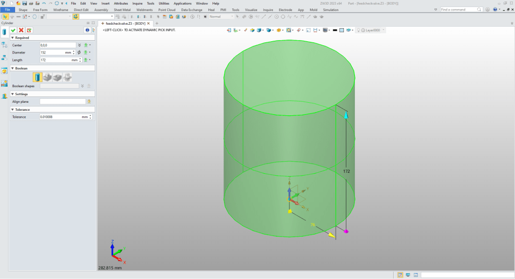
We insert a cylinder at X0Y0Z0 and size it.
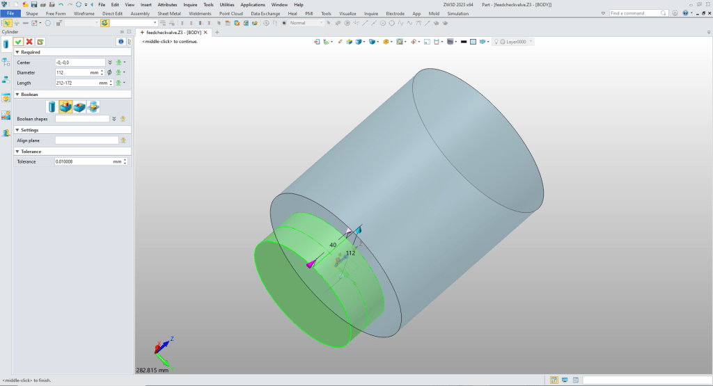
We will now insert another cylinder at the bottom center of the existing cylinder, size it and set it to add.
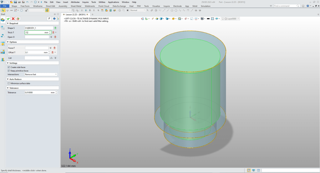
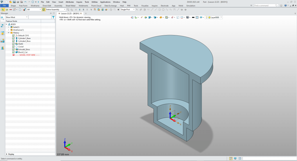
We did a design intent evaluation and realized this shape could be shelled.
So we shell with no open faces.
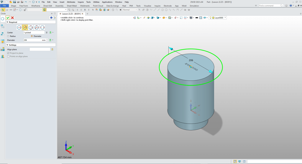
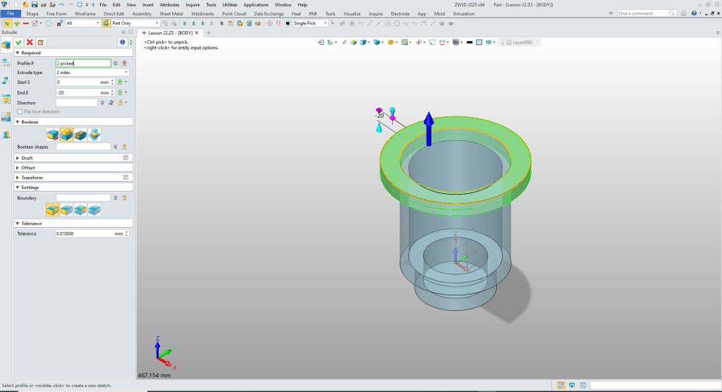
We create the flange by using the wireframe tab to create a circle using the wire at the top center of the cylinder as shown. Again ZW3D recognizes the center automatically. We size the circle.
We now select extrude select the outside circle and the outside edge of the cylinder and create the flange, set the depth and set to add. This saves the step of creating a sketch.
We insert a temp block, size it and set it to remove. You can see we have the basic shape. No sketches.
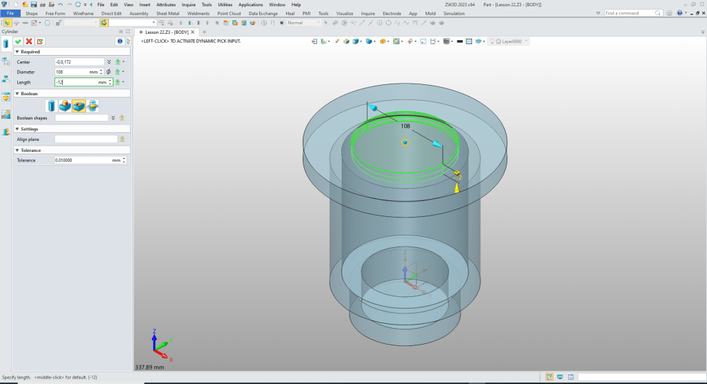
Now will will add the hole in the top by inserting a cylinder and sizing it.
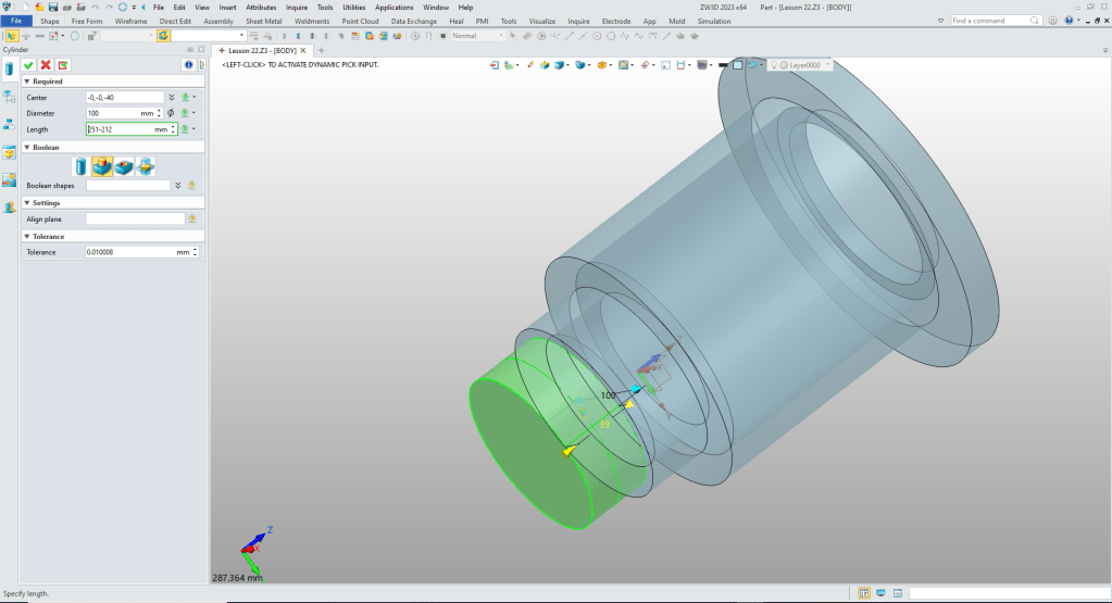
We have to add a cylinder to the bottom.
Now for the bottom flange. We insert a cylinder at the center of the bottom cylinder an size it.
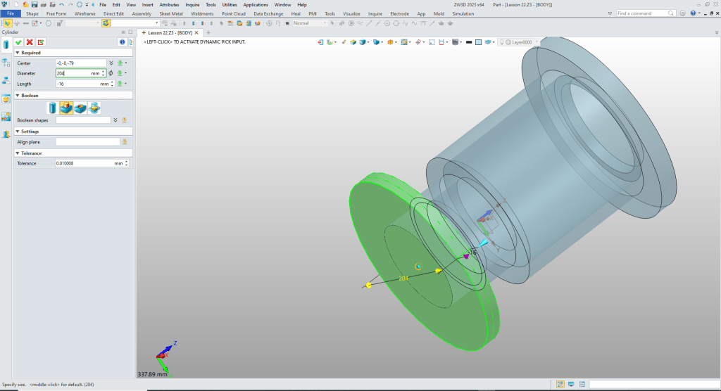
We will insert a cylinder at the center of the flanged to create the hole.
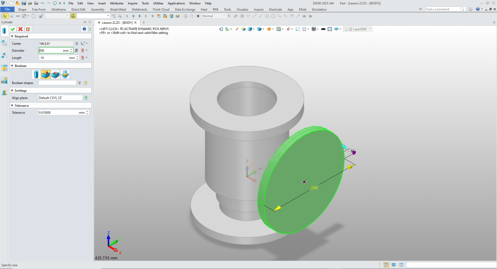
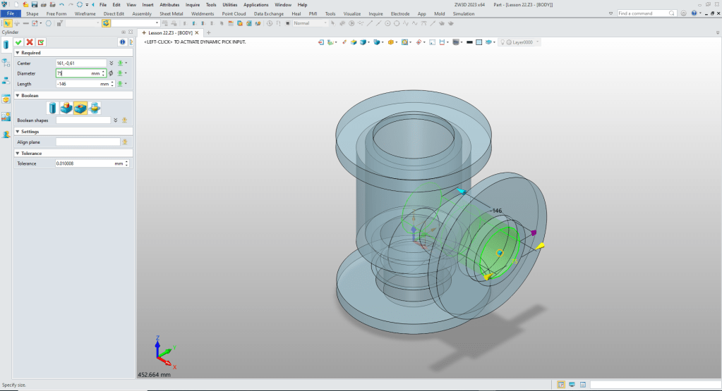
Now we will create the horizontal flange. You will see why later. We again insert a cylinder locate it and size it. This will create two separate solids.
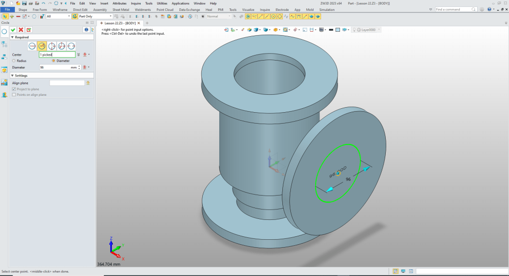
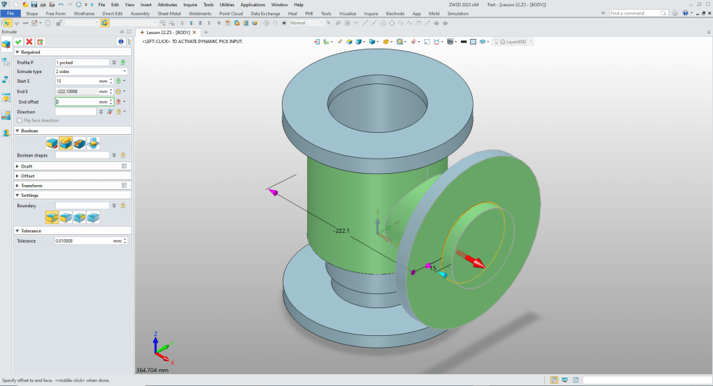
I really like this feature. I am not sure how many CAD system have it. But it eliminates creating a sketch yet still editable. Using the wireframe features we will create a circle on the face of the horizontal cylinder and size it.
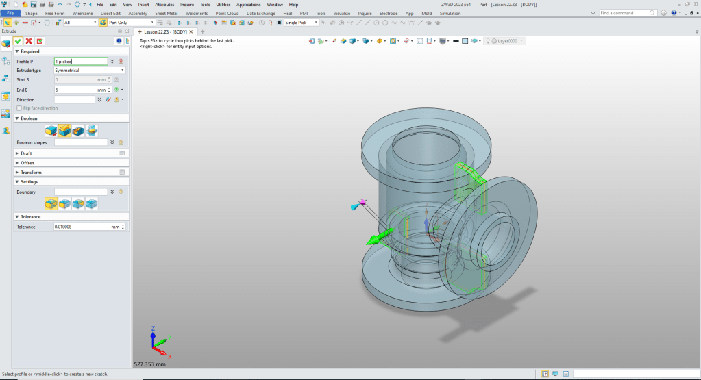
I had to create an extrusion. The primitives do not allow extend to face. We will extrude the circle. Set the front depth and set the other to face. We had two solids with this step they now become one.
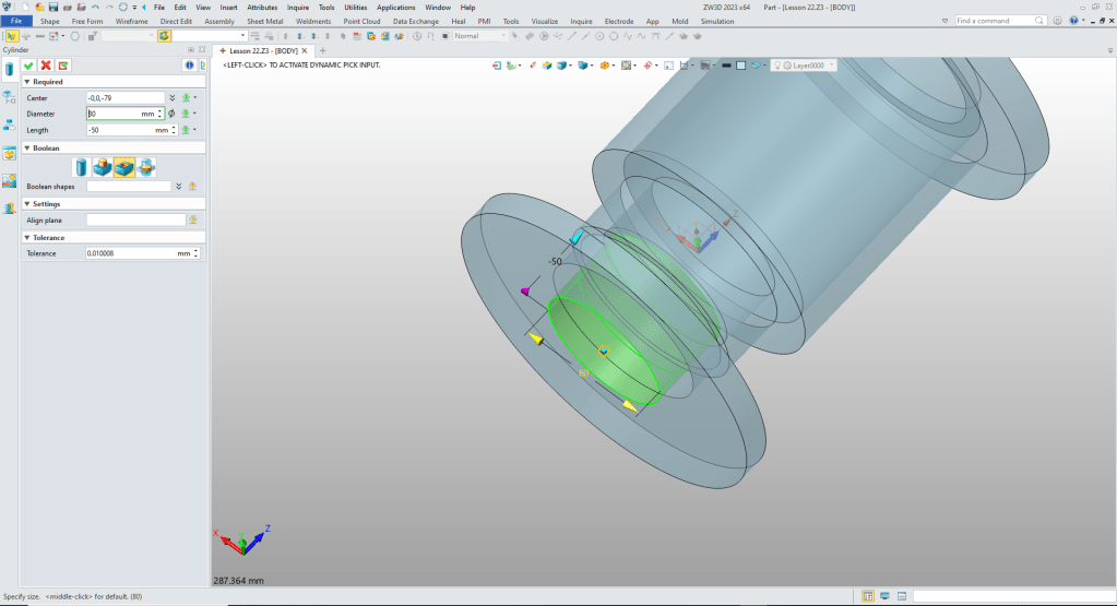
Now the hole. We insert a cylinder at the center of the cylinder and size it.
We now need to create some fillets. I inserted block sized and set to remove so we can see the state of the model.
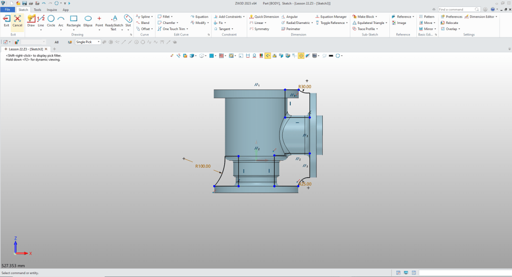
We have to create the ribs. So we will create a sketch on the XZ plane.
We extrude the rib.
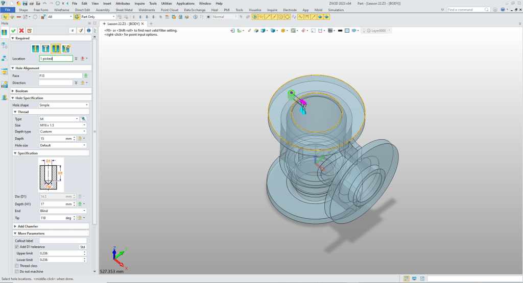
We put the threaded holes in the top flange.
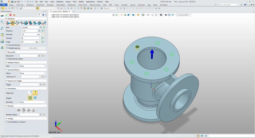
We pattern the holes.
We create the hole pattern the bottom and horizontal flange and we are done.
It is very important that you look into how you or your engineers are creating the parts. Streamline Sketching and Feature Based Modeling is easy to learn and implement. It, alone, will increase productivity 10X. Now, IronCAD with its unique integrated history/direct edit functionality can increase your productivity another 5X or more with changes! Again, time is money in engineering.
More on Streamline Sketching and Feature Based Modeling.
3D Modeling Techniques Defined
To experience this increased level of productivity, please download ZW3D for a 30 day evaluation. Legacy data is no problem, ZW3D can read the native files of all of the popular programs. ZW3D is a great replacement for the subscription only Autodesk and PTC products.
For more information or to download ZW3D
Give me a call if you have any questions. I can set up a skype or gotomeeting to show this part or answer any of your questions on the operation of IronCAD. It truly is the very best conceptual 3D CAD system.
TECH-NET Engineering Services!
We sell and support IronCAD and ZW3D Products and
provide engineering services throughout the USA and Canada!
Why TECH-NET Sells IronCAD and ZW3D
If you are interested in adding professional hybrid modeling capabilities or looking for a new solution to increase your productivity, take some time to download a fully functional 30 day evaluation and play with these packages. Feel free to give me a call if you have any questions or would like an on-line presentation.
For more information or to download IronCAD or ZW3D
Joe Brouwer
206-842-0360
